background image

Publication No. CPCI3UX606-HRM/1

CPCI3UX606 11

1.4.7 P7 (SATA1)

NOTE

Availability of signals at this connector depends on the build option selected on the IMP3A.

Use


a


right

angled


SATA


cable


to


remain


within


the


allowable


height


limit.

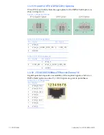
1.4.8 P8 (COM1)

See


the


P2


description


for


more


details


on


COM1.

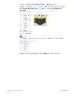
Table 1-11 P6 Pin Assignments

Pin

Signal

1

GND

2

S

3

SATA1_TX-

4

GND

5

SATA1_RX-

6

S

7

GND

Table 1-12 P8 Pin Assignments

Pin

Signal

Pin Signal

1

No connection

6

No connection

2

COM1_RXD (RXD_A)

7

COM1_CTS (RXD_B)

3

COM1_TXD (TXD_A)

8

COM1_RTS (TXD_B)

4

No connection

9

No connection

5

GND

Summary of Contents for CPCI3UX606

Page 1: ...Hardware Reference Manual CPCI3UX606 First Edition Publication No CPCI3UX606 HRM 1 GE Intelligent Platforms...

Page 2: ...PCS and subject to suitable contractual arrangements being in place will ensure WEEE is processed in accordance with the requirements of the WEEE Directive GE Intelligent Platforms Limited will evalu...

Page 3: ...ivity 6 1 4 Pin Assignments 7 1 4 1 P1 Ethernet Gigabit Signals 7 1 4 2 P2 COM1 COM2 7 1 4 3 P3 GPIO 8 1 4 4 P4 PMC 1 to 32 I O 9 1 4 5 P5 PMC 33 to 64 I O 10 1 4 6 P6 SATA0 10 1 4 7 P7 SATA1 11 1 4 8...

Page 4: ...Description The CPCI3UX606 module is a customized interface adapter compatible with 3U CompactPCI backplanes It fits directly onto the rear P2 position of the backplane and is only suitable for interc...

Page 5: ...PCB Male Header ID Function Pin Signal E1 BIT_FAIL open drain output USB powera a Function depends on the build option selected 1 USB_PWR 2 GND E2 RTC_STDBY input 1 RTC_STDBY 2 GND E3 Push button res...

Page 6: ...ector Function Type P1 Ethernet Gigabit Signals Male header P2 COM1 COM2 Male header P3 GPIO Male header P4 PMC 1 to 32 I O Male header P5 PMC 33 to 64 I O Male header P6 SATA0 Molex header P7 SATA1 M...

Page 7: ...h is an IMP3A build option also see P9 and P10 RS232 RS422 configuration of COM1 is software controlled RS422 option signals are given in parentheses COM2 is 4 wire permanently RS232 RS422 configurati...

Page 8: ...ion selected on the IMP3A Table 1 7 P3 Pin Assignments Pin Signal Pin Signal 1 GPIO0 2 GND 3 GPIO1 4 GND 5 GPIO2 6 GND 7 GPIO3 8 GND 9 GPIO4 10 GND 11 GPIO5 12 GND 13 GPIO6 14 GND 15 GPIO7 16 GND 17 G...

Page 9: ...4 1 2 J14 2 3 J14 3 4 J14 4 5 J14 5 6 J14 6 7 J14 7 8 J14 8 9 J14 9 10 J14 10 11 J14 11 12 J14 12 13 J14 13 14 J14 14 15 J14 15 16 J14 16 17 J14 17 18 J14 18 19 J14 19 20 J14 20 21 J14 21 22 J14 22 23...

Page 10: ...right angled SATA cable to remain within the allowable height limit Table 1 9 P5 Pin Assignments Pin Signal Pin Signal 1 J14 33 2 J14 34 3 J14 35 4 J14 36 5 J14 37 6 J14 38 7 J14 39 8 J14 40 9 J14 41...

Page 11: ...main within the allowable height limit 1 4 8 P8 COM1 See the P2 description for more details on COM1 Table 1 11 P6 Pin Assignments Pin Signal 1 GND 2 SATA1_TX 3 SATA1_TX 4 GND 5 SATA1_RX 6 SATA1_RX 7...

Page 12: ...on depends on availability of the required signals which is an IMP3A build option see also P1 10 100 signals are given in parentheses Table 1 13 P9 Pin Assignments Pin Signal Pin Signal 1 ETH1_3 3 ETH...

Page 13: ...10 100 signals are given in parentheses 1 4 12 J5 USB NOTE Availability of signals at this connector depends on the build option selected on the IMP3A The IMP3A provides USB_PWR when a USB build optio...

Page 14: ...14 CPCI3UX606 Publication No CPCI3UX606 HRM 1 Figure 1 4 CPCI3UX606 with Front Panel Figure 1 5 CPCI3UX606 in Rear Guide Rails per IEEE1101 11...

Page 15: ...IONS OR WARRANTIES OF ANY KIND WHETHER EXPRESS OR IMPLIED INCLUDING BUT NOT LIMITED TO WARRANTIES OF DESIGN MERCHANTABILITY OR FITNESS FOR A PARTICULAR PURPOSE ALL OTHER LIABILITY ARISING FROM RELIANC...

Reviews: