Publication No. CPCI3UX606-HRM/1
CPCI3UX606 5
1.2 Connector and Header Designations
CAUTION
Do not fit a jumper across the E1 pins. If a build option that provides USB has been selected, linking
these pins will short USB_PWR to ground, which may cause damage to the IMP3A.
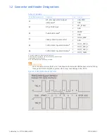
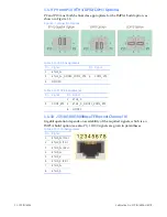
Figure 1-2 RS422/485 Signal Definition
Table 1-1 Headers
PCB Male Header ID
Function
Pin
Signal
E1
BIT_FAIL open-drain output/
USB power
a
a. Function depends on the build option selected.
1
USB_PWR
2
GND
E2
RTC_STDBY input
1
RTC_STDBY
2
GND
E3
Push-button reset
b
b.A push-button reset switch can be connected across these pins.
1
PRST#
2
GND
E4
Flash protection unlock link
c
c. Not available on Rev 1 boards.
1
FLASH_WE#
2
GND
E5
COM1 RS422 input termination
d
d.120
Ω
termination selected when pins linked.
1
COM1_RXD_A
2
COM1_RXD_B
E6
COM2 RS422 input termination
b
1
COM2_RXD_A
2
COM2_TERM


