GE Multilin
D30 Line Distance Protection System
9-19
9 THEORY OF OPERATION
9.4 SERIES COMPENSATED LINES
9
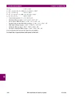
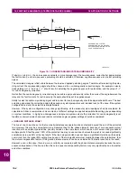
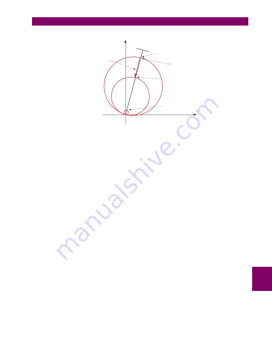
Figure 9–7: DYNAMIC REACH CONTROL
Section (a) of the figure below shows the effect of adaptive reach control for low-current external fault. The reach is reduced
sufficiently to cope with both transient and steady-state overreach. Section (b) shows a high-current external fault. The air
gaps or MOVs conduct majority of the fault current and neither steady-state nor transient overreach takes place. The relay
does not reduce its reach as it is not necessary. Section (c) shows a high-current internal fault. Because of the large cur-
rent, the reach is not reduced and the element responds to this internal fault. Traditional approach would leave this fault out
of the relay reach.
The neutral and negative-sequence directional protection functions of the relay cope with the voltage and/or current inver-
sions by adding appropriate offset to their polarizing signals as explained in the Ground Directional Overcurrent section.
The offset impedance can always be successfully selected to guarantee correct fault direction discrimination regardless of
the degree of compensation and location of the series capacitors and the potential source.
Refer to Chapter 9: Application of Settings for detailed recommendations on settings for series compensation applications.
837729A1.CDR
THE REACH IS
DYNAMICALLY
REDUCED BY
V
L
/abs(I)
SET REACH (
Z
R
)
ACTUAL REACH IS
A FUNCTION OF
CURRENT
MAGNITUDE
ACTUAL REACH
FOR VERY HIGH
CURRENTS
ACTUAL REACH
FOR VERY SMALL
CURRENTS
R
X
FAR-E
ND
BUSB
AR
Summary of Contents for D30D00HCHF8AH6AM6BP8BX7A
Page 10: ...x D30 Line Distance Protection System GE Multilin TABLE OF CONTENTS...
Page 374: ...5 248 D30 Line Distance Protection System GE Multilin 5 10 TESTING 5 SETTINGS 5...
Page 398: ...6 24 D30 Line Distance Protection System GE Multilin 6 5 PRODUCT INFORMATION 6 ACTUAL VALUES 6...
Page 410: ...7 12 D30 Line Distance Protection System GE Multilin 7 2 TARGETS 7 COMMANDS AND TARGETS 7...
Page 444: ...9 24 D30 Line Distance Protection System GE Multilin 9 5 FAULT LOCATOR 9 THEORY OF OPERATION 9...
Page 576: ...B 102 D30 Line Distance Protection System GE Multilin B 4 MEMORY MAPPING APPENDIX B B...
Page 616: ...D 10 D30 Line Distance Protection System GE Multilin D 1 IEC 60870 5 104 PROTOCOL APPENDIX D D...
Page 628: ...E 12 D30 Line Distance Protection System GE Multilin E 2 DNP POINT LISTS APPENDIX E E...
Page 636: ...F 8 D30 Line Distance Protection System GE Multilin F 3 WARRANTY APPENDIX F F...
Page 646: ...x D30 Line Distance Protection System GE Multilin INDEX...


