GE Multilin
D30 Line Distance Protection System
10-3
10 APPLICATION OF SETTINGS
10.2 DISTANCE ELEMENTS (STEPPED DISTANCE SCHEME)
10
ation should also be given to a situation where the load impedance may enter into the relay characteristic for a time longer
than the chosen time delay, which could occur transiently during a system power swing. For this reason the power swing
blocking function should be used.
e) PHASE DISTANCE ZONE 4
A further contribution to remote backup, the reach of this element must be set to account for any infeed at the remote bus.
The time delay must coordinate with other time-delayed protections on the next line. The use of a lens characteristic or the
load encroachment element may be advantageous if load limits are a problem.
To avoid extremely large reach settings, the D30 has the ability to implement any element so that it is reverse looking,
which then can provide a back up for the longest line terminated on the local bus. This strategy can be beneficial if the
reduced reach helps discrimination between the load and fault conditions, but must be implemented at both ends of the
protected line.
f) PHASE DISTANCE ZONE 5
An additional fifth phase distance zone can be used in special applications. This zone may be start zone for arming tripping
from all other zones, in both forward and reverse directions of the of protected line. This zone may also be used as an addi-
tional reverse-looking zone for implementation of two reverse-looking zones, thus providing two zone backup reverse-look-
ing protection. The fifth distance zone can be used as an alarm zone, indicating that load impedance is approaching the
zone characteristic.
10.2.2 GROUND DISTANCE
a) NEUTRAL CURRENT SUPERVISION
The current supervision for the ground distance elements responds to an internally calculated neutral current (3 × I_0). The
setting for this element should be based on twice the zero-sequence line capacitance current or the maximum zero-
sequence unbalance under maximum load conditions. This element should not be used to prevent an output when the load
impedance is inside the distance characteristic on a steady state basis.
b) POLARIZING CURRENT AND NON-HOMOGENEITY CORRECTION ANGLE OF THE QUAD CHARACTERISTIC
An ideal reactance line for single-line-to-ground faults is polarized from the fault current flowing through the fault resistance.
Such a line defines constant reach and could be implemented by the following angle comparator:
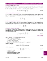
(EQ 10.1)
The relay could only approximate the unknown fault current by the zero-sequence or the negative-sequence currents mea-
sured at the relaying point. Depending on system parameters, either the zero-sequence or the negative-sequence current
presents better approximation of the fault current angle.
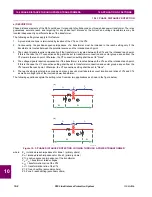
Given the equivalent systems shown in the figure below, the angular difference between the zero-sequence or negative-
sequence currents at the relay, and the fault current can be calculated as follows:
(EQ 10.2)
(EQ 10.3)
where:
A
is the local equivalent system
B
is the remote equivalent system
L
is the line
d
is the per-unit (pu) intended reach of the zone (typically 0.7 to 0.9).
I Z
×
V
vs.
j I
F
×
–
Θ
0
angle
I
F
I
0_RELAY
----------------------
angle
Z
0
A
Z
0
L
Z
0
B
+
+
Z
0
B
1
d
–
(
)
Z
0
L
+
-------------------------------------------
=
=
Θ
2
angle
I
F
I
2_RELAY
----------------------
angle
Z
1
A
Z
1
L
Z
1
B
+
+
Z
1
B
1
d
–
(
)
Z
1
L
+
-------------------------------------------
=
=
Summary of Contents for D30D00HCHF8AH6AM6BP8BX7A
Page 10: ...x D30 Line Distance Protection System GE Multilin TABLE OF CONTENTS...
Page 374: ...5 248 D30 Line Distance Protection System GE Multilin 5 10 TESTING 5 SETTINGS 5...
Page 398: ...6 24 D30 Line Distance Protection System GE Multilin 6 5 PRODUCT INFORMATION 6 ACTUAL VALUES 6...
Page 410: ...7 12 D30 Line Distance Protection System GE Multilin 7 2 TARGETS 7 COMMANDS AND TARGETS 7...
Page 444: ...9 24 D30 Line Distance Protection System GE Multilin 9 5 FAULT LOCATOR 9 THEORY OF OPERATION 9...
Page 576: ...B 102 D30 Line Distance Protection System GE Multilin B 4 MEMORY MAPPING APPENDIX B B...
Page 616: ...D 10 D30 Line Distance Protection System GE Multilin D 1 IEC 60870 5 104 PROTOCOL APPENDIX D D...
Page 628: ...E 12 D30 Line Distance Protection System GE Multilin E 2 DNP POINT LISTS APPENDIX E E...
Page 636: ...F 8 D30 Line Distance Protection System GE Multilin F 3 WARRANTY APPENDIX F F...
Page 646: ...x D30 Line Distance Protection System GE Multilin INDEX...

