10-6
D30 Line Distance Protection System
GE Multilin
10.3 SERIES COMPENSATED LINES
10 APPLICATION OF SETTINGS
10
10.3SERIES COMPENSATED LINES
10.3.1 INTRODUCTION
For reasons described in Chapter 8:
Theory of Operation
, it is recommended to apply a combination of distance, ground
directional overcurrent and high-set overcurrent functions for protection of series compensated lines.
The setting rules described below must take into account variety of system configurations, particularly a status of series
capacitors (in-service, by-passed). Either the worst-case topology shall be considered or - if possible - adaptive settings
shall be applied though the multiple settings groups mechanism.
A line compensating capacitor is a bank of three physical capacitors and their overvoltage protecting devices (air gaps and/
or MOVs). If none of the MOV/gaps conducts any significant current, the positive-, negative- and zero-sequence reactance
of the three-phase bank equal the reactance of the actual (phase) capacitors. Under asymmetrical conditions, however,
such as a single line to ground fault, when only one MOV/gap may operate, the series capacitor bank would create extra
(series) asymmetry in addition to the fault (shunt) asymmetry. The positive-, negative- and zero-sequence impedances will
differ from each other and will not equal the impedance of the phase capacitors. Moreover, there may be mutual coupling
between the sequence networks representing the series capacitor bank. This makes analytical analysis of fault conditions
very burdensome. For setting calculations, however, it is justified to assume the zero-, positive-, and negative-sequence
reactance of the capacitor bank equal the reactance of the actual (phase) capacitors. This represents a worst-case low-cur-
rent fault scenario, when the steady-state effects of series compensation are most weighty.
10.3.2 DISTANCE
Traditionally, the reach setting of an underreaching distance function shall be set based on the net inductive impedance
between the potential source of the relay and the far-end busbar, or location for which the zone must not overreach. Faults
behind series capacitors on the protected and adjacent lines need to be considered for this purpose. For further illustration
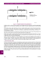
a sample system shown in the figure below is considered.
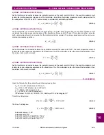
Figure 10–2: SAMPLE SERIES COMPENSATED SYSTEM
Assuming 20% security margin, the underreaching zone shall be set as follows.
At the Sending Bus, one must consider an external fault at F1 as the 5
Ω
capacitor would contribute to the overreaching
effect. Any fault behind F1 is less severe as extra inductive line impedance increases the apparent impedance:
Reach Setting: 0.8 x (10 – 3 – 5) = 1.6
Ω
if the line-side (B) VTs are used
Reach Setting: 0.8 x (10 – 4 – 3 – 5) = –1.6
Ω
if the bus-side (A) VTs are used
The negative value means that an underreaching zone cannot be used as the circuit between the potential source of the
relay and an external fault for which the relay must not pick-up, is overcompensated, i.e. capacitive.
At the Receiving Bus, one must consider a fault at F2:
Reach Setting: 0.8 x (10 – 4 – 2) = 3.2
Ω
if the line-side (B) VTs are used
Reach Setting: 0.8 x (10 – 4 – 3 – 2) = 0.8
Ω
if the bus-side (A) VTs are used
Practically, however, to cope with the effect of sub-synchronous oscillations, one may need to reduce the reach even more.
As the characteristics of sub-synchronous oscillations are in complex relations with fault and system parameters, no solid
setting recommendations are given with respect to extra security margin for sub-synchronous oscillations. It is strongly rec-
ommended to use a power system simulator to verify the reach settings or to use an adaptive D30 feature for dynamic
reach control.
If the adaptive reach control feature is used, the
PHS DIST Z1 VOLT LEVEL
setting shall be set accordingly.
10
Ω
-4
Ω
-3
Ω
-5
Ω
7
Ω
-2
Ω
3
Ω
SENDING
BUS
RECEIVING
BUS
Protected Line
A B
B A
IN
FIN
ITE
BU
S
IN
FIN
ITE
BU
S
F1
F2
0.5 pu
0.6 pu
0.5 pu
0.7 pu
reactance
voltage
protection
level
Summary of Contents for D30D00HCHF8AH6AM6BP8BX7A
Page 10: ...x D30 Line Distance Protection System GE Multilin TABLE OF CONTENTS...
Page 374: ...5 248 D30 Line Distance Protection System GE Multilin 5 10 TESTING 5 SETTINGS 5...
Page 398: ...6 24 D30 Line Distance Protection System GE Multilin 6 5 PRODUCT INFORMATION 6 ACTUAL VALUES 6...
Page 410: ...7 12 D30 Line Distance Protection System GE Multilin 7 2 TARGETS 7 COMMANDS AND TARGETS 7...
Page 444: ...9 24 D30 Line Distance Protection System GE Multilin 9 5 FAULT LOCATOR 9 THEORY OF OPERATION 9...
Page 576: ...B 102 D30 Line Distance Protection System GE Multilin B 4 MEMORY MAPPING APPENDIX B B...
Page 616: ...D 10 D30 Line Distance Protection System GE Multilin D 1 IEC 60870 5 104 PROTOCOL APPENDIX D D...
Page 628: ...E 12 D30 Line Distance Protection System GE Multilin E 2 DNP POINT LISTS APPENDIX E E...
Page 636: ...F 8 D30 Line Distance Protection System GE Multilin F 3 WARRANTY APPENDIX F F...
Page 646: ...x D30 Line Distance Protection System GE Multilin INDEX...


