148
D90
PLUS
LINE DISTANCE PROTECTION SYSTEM – INSTRUCTION MANUAL
DIRECT INPUTS AND OUTPUTS
CHAPTER 6: COMMUNICATIONS
Message Alarm Function
Range: Enabled, Disabled
Default: Disabled
The D90
Plus
checks integrity of the direct input/output communication ring by counting
unreturned messages. In the ring configuration, all messages originating at a given
device should return within a pre-defined period of time. The unreturned messages
alarm function is available for monitoring the integrity of the communication ring by
tracking the rate of unreturned messages. This function counts all the outgoing
messages and a separate counter adds the messages have failed to return.
The unreturned messages alarm function is available on a per-channel basis and is
active only in the ring configuration. The total number of unreturned input/output
messages is available as an actual value.
Message Alarm Count
Range: 100 to 10000 in steps of 1
Default: 600
When the total message counter reaches the user-defined maximum specified by this
setting, both the counters reset and the monitoring process is restarted.
Message Alarm Threshold
Range: 1 to 1000 in steps of 1
Default: 10
When the unreturned messages counter reaches the user-definable level specified by
this setting and within the user-defined message count specified by
Channel 1 Msg
Alarm Count
, the
DIR IO CH1 UNRET ALM
FlexLogic™ operand is set. The operand shall be
configured to drive an output contact, annunciator alarm, or selected communication-
based output. Latching and acknowledging conditions, if required, should be
programmed accordingly in the annunciator settings.
Message Alarm Events
Range: Enabled, Disabled
Default: Disabled
This setting enables and disables the logging of unreturned message alarm events in the
sequence of events recorder.
Direct input and output applications
The following application examples illustrate the basic concepts for direct input and output
configuration.
Using direct inputs and outputs to extend input/output capabilities
Consider an application that requires additional contact inputs or outputs or lines of
programmable logic that exceed the capabilities of a single UR
Plus
-series device. The
problem is solved by adding an extra UR
Plus
-series IED to satisfy the additional input and
output and programmable logic requirements. The two IEDs are connected via single-
channel digital communication cards as shown below.
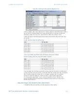
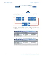
Figure 120: Input and output extension via direct inputs and outputs
$&'5
85
VHULHV,('
3OXV
7;
5;
85
VHULHV,('
3OXV
5;
7;

