170
D90
PLUS
LINE DISTANCE PROTECTION SYSTEM – INSTRUCTION MANUAL
POWER SYSTEM
CHAPTER 7: PROTECTION
User Configuration Name
Range: up to 20 alphanumeric characters
Default: Initial
This setting allows the user to provide a description for the settings that are loaded at a
particular time (for example, “Spring-summer settings”). This description is displayed on
the Product Information page of the front panel annunciator under the
Configuration
field.
User Configuration Date
Range: up to 20 alphanumeric characters
Default: -----
This setting records the date of last setting change through the EnerVista UR
Plus
Setup software. Each time any settings are changed or a new settings file loaded, this
value is updated. This description is also displayed on the Product Information page of
the front panel annunciator under the
Date
field directly to the right of the
Configuration
field.
AC input modules
CT and VT input channels are contained in AC modules. The following input channel types
are available.
•
Three-phase voltage.
•
Single-phase auxiliary voltage.
•
Three-phase current.
•
Single-phase ground current.
The AC modules calculate total waveform RMS levels, fundamental frequency phasors, and
symmetrical components, as allowed by the hardware in each channel. These modules
may calculate other parameters as directed by the CPU module.
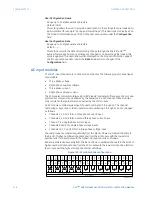
An AC module contains twelve input channels, numbered 1 through 12. The channel
numbering corresponds to the module terminal numbering 1 through 12 and is arranged
as follows.
•
Channels 1, 2, and 3 form a three-phase current input.
•
Channels 4, 5, and 6 form a second three-phase current input.
•
Channel 7 is a single-phase current input.
•
Channels 8 and 9 are single-phase voltage inputs.
•
Channels 10, 11, and 12 form a three-phase voltage input.
Channel groups are ordered sequentially from the block of lower-numbered channels to
the block of higher-numbered channels, and from the AC module with the lowest slot
position letter to the module with the highest slot position letter, as follows:
Banks are ordered sequentially from the block of lower-numbered channels to the block of
higher-numbered channels, and from the AC module with the lowest slot position letter to
the module with the highest slot position letter, as follows.
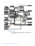
Figure 150: AC module bank configuration
$&'5
a
E
a
E
a
D
a
D
a
E
a
D
a
E
a
E
a
D
92/7$*(,13876
&855(17,13876
a
D
a
E
a
E
a
D
a
D
a
E
a
D
a
E
a
D
a
E
a
D
a
E
a
D
a
E
,$
,%
,&
,%
,&
,$
,$
,%
,%
,&
,&
,*
,*
9;
9;
9;
9;
9$
9$
9%
9%
9&
9&
a
D
,$
$&02'8/(

