


208
D90
PLUS
LINE DISTANCE PROTECTION SYSTEM – INSTRUCTION MANUAL
GROUPED PROTECTION ELEMENTS
CHAPTER 7: PROTECTION
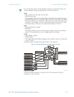
first step is similar to the power swing blocking sequence. After the timer specified by the
Pickup Delay 1
setting times out, latch 1 is set as long as the impedance stays within the
outer characteristic.
If afterwards, at any time (given the impedance stays within the outer characteristic), the
locus enters the middle characteristic but stays outside the inner characteristic for a
period of time defined by the
Pickup Delay 2
setting, latch 2 is set as long as the impedance
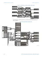
stays inside the outer characteristic. If afterwards, at any time (given the impedance stays
within the outer characteristic), the locus enters the inner characteristic and stays there for
a period of time defined the Pickup Delay 3 setting, latch 2 is set as long as the impedance
stays inside the outer characteristic; the element is now ready to trip.
If the Early trip mode is selected, the
POWER SWING TRIP
operand is set immediately and
sealed-in for the interval specified by the
Seal-In Delay
setting. If the “Delayed” trip mode is
selected, the element waits until the impedance locus leaves the inner characteristic, then
times out for the
Pickup Delay 2
setting and sets latch 4; the element is now ready to trip.
The trip operand is set later, when the impedance locus leaves the outer characteristic.
The two-step mode of operation is similar to the three-step mode with two exceptions.
1.
The initial stage monitors the time spent by the impedance locus between the outer
and inner characteristics.
2.
Second, the stage involving the
Pickup Delay 2
timer is bypassed. It is up to the user to
integrate the blocking (
POWER SWING BLOCK
) and tripping (
POWER SWING TRIP
)
FlexLogic™ operands with other protection functions and output contacts in order to
make this element fully operational.
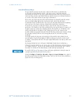
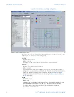
The element can be set to use either lens (mho) or rectangular (quad) characteristics as
illustrated below. When set to “Mho”, the element applies the right and left blinders as well.
If the blinders are not required, their settings should be set high enough to effectively
disable the blinders.
Figure 184: Power swing detect mho operating characteristic
2XW
HU
0LGGOH
,QQHU
0LGGOH/LPLW
$QJOH
2XWHU/LPLW$QJOH
$&'5
)R
UZ
DU
G5
HDFK
5
;
)RUZDUG
5&$
5HYHUVH5HDFK
5HYHUVH
5&$
,QQHU/LPLW$QJOH


