CHAPTER 7: PROTECTION
GROUPED PROTECTION ELEMENTS
D90
PLUS
LINE DISTANCE PROTECTION SYSTEM – INSTRUCTION MANUAL
239
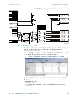
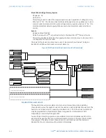
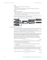
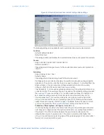
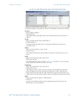
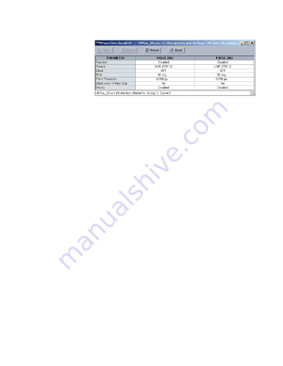
Figure 203: Phase directional overcurrent configuration settings
The following settings are available for each phase directional overcurrent element.
Function
Range: Enabled, Disabled
Default: Disabled
This setting enables and disables the phase directional overcurrent protection element.
Source
Range: LINE (SRC 1), BKR 1 (SRC 2), BKR 2 (SRC 3)
Default: LINE (SRC 1)
This setting is used to select the source for the operating and polarizing signals. The
operating current for the phase directional element is the phase current for the selected
current source. The polarizing voltage is the line voltage from the phase VTs, based on
the 90° or quadrature connection and shifted in the leading direction by the element
characteristic angle (ECA).
Block
Range: any FlexLogic™ operand or shared operand
Default: Off
Assertion of the operand assigned to this setting blocks operation of the phase
directional overcurrent element.
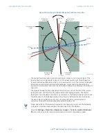
ECA
Range: 0 to 359° in steps of 1
Default: 30°
This setting specifies the element characteristic angle; that is, the angle by which the
polarizing voltage is shifted in the leading direction to achieve dependable operation. In
the design of the D90
Plus
protection elements, a block is applied to an element by
asserting logic 1 at the blocking input. The phase directional overcurrent element should
be programmed via this setting so that the output is logic 1 for current in the non-
tripping direction.
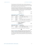
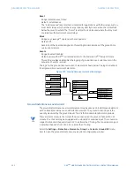
Polarizing Voltage Threshold
Range: 0.000 to 3.000 pu in steps of 0.001
Default: 0.700 pu
This setting is used to establish the minimum level of voltage for which the phase angle
measurement is reliable. The setting is based on VT accuracy.


