260
D90
PLUS
LINE DISTANCE PROTECTION SYSTEM – INSTRUCTION MANUAL
GROUPED PROTECTION ELEMENTS
CHAPTER 7: PROTECTION
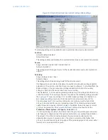
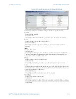
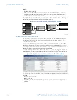
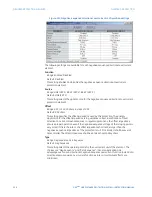
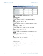
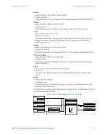
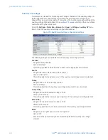
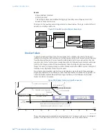
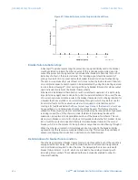
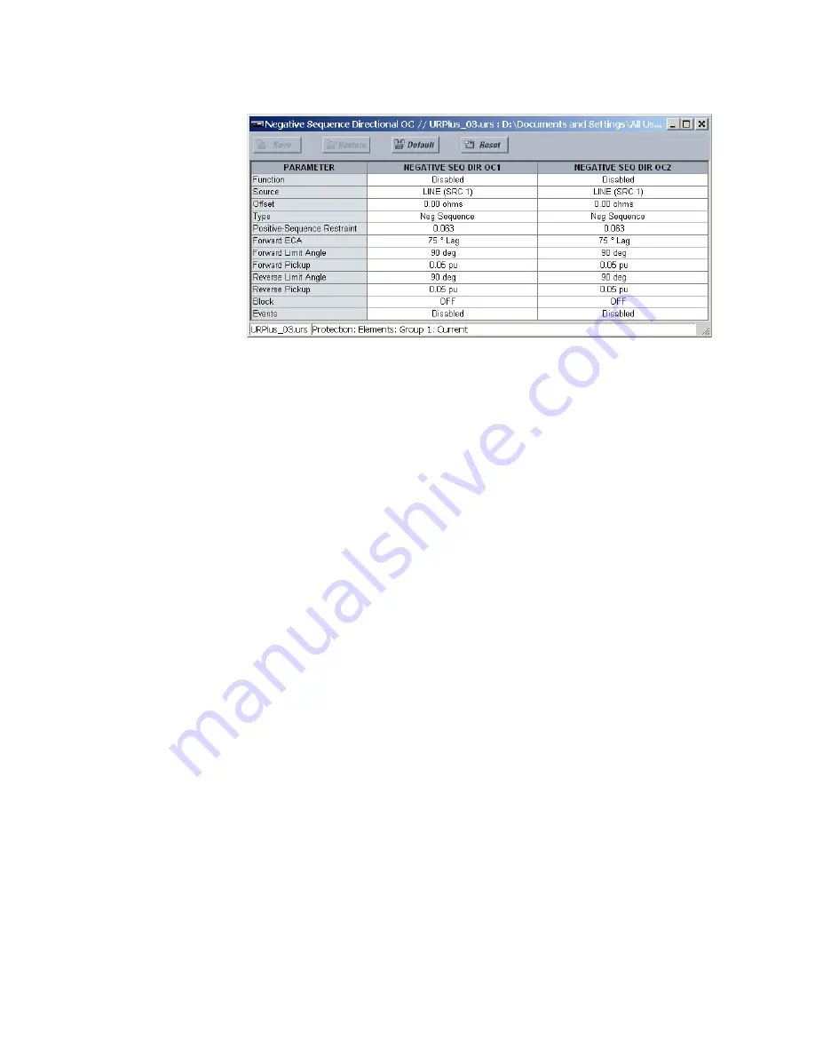
Figure 221: Negative-sequence directional overcurrent configuration settings
The following settings are available for each negative-sequence directional overcurrent
element.
Function
Range: Enabled, Disabled
Default: Disabled
This setting enables and disables the negative-sequence directional overcurrent
protection element.
Source
Range: LINE (SRC 1), BKR 1 (SRC 2), BKR 2 (SRC 3)
Default: LINE (SRC 1)
This setting selects the signal source for the negative-sequence directional overcurrent
protection element.
Offset
Range: 0.00 to 250.00 ohms in steps of 0.01
Default: 0.00 ohms
This setting specifies the offset impedance used by this protection. The primary
application for the offset impedance is to guarantee correct identification of fault
direction on series compensated lines. In regular applications, the offset impedance
ensures proper operation even if the negative-sequence voltage at the relaying point is
very small. If this is the intent, the offset impedance shall not be larger than the
negative-sequence impedance of the protected circuit. Practically, it shall be several
times smaller. The offset impedance shall be entered in secondary ohms.
Type
Range: Neg Sequence, Zero Sequence
Default: Neg Sequence
This setting selects the operating mode for the overcurrent unit of the element. The
choices are “Neg Sequence” and “Zero Sequence”. In some applications it is
advantageous to use a directional negative-sequence overcurrent function instead of a
directional zero-sequence overcurrent function as inter-circuit mutual effects are
minimized.

