CHAPTER 7: PROTECTION
GROUPED PROTECTION ELEMENTS
D90
PLUS
LINE DISTANCE PROTECTION SYSTEM – INSTRUCTION MANUAL
267
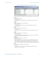
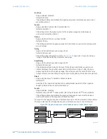
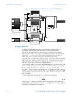
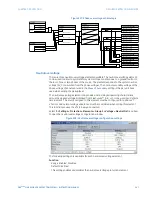
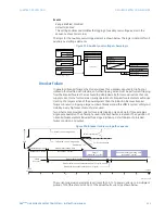
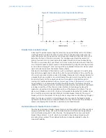
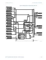
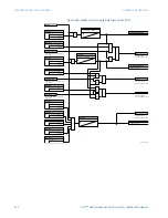
Figure 227: Phase overvoltage scheme logic
Neutral overvoltage
There are three neutral overvoltage elements available. The neutral overvoltage element
can be used to detect asymmetrical system voltage condition due to a ground fault or to
the loss of one or two phases of the source. The element responds to the system neutral
voltage (3V_0), calculated from the phase voltages. The nominal secondary voltage of the
phase voltage channels entered in the
Phase VT Secondary
setting is the per-unit base
used when setting the pickup level.
The neutral overvoltage element can provide a time-delayed operating characteristic
versus the applied voltage (initialized from FlexCurves™ A, B, or C) or be used as a definite
time element. The source assigned to this element must be configured for a phase VT.
VT errors and normal voltage unbalance must be considered when setting this element.
This function requires the VTs to be wye-connected.
Select the
Settings > Protection > Elements > Group 1 > Voltage > Neutral OV
menu item
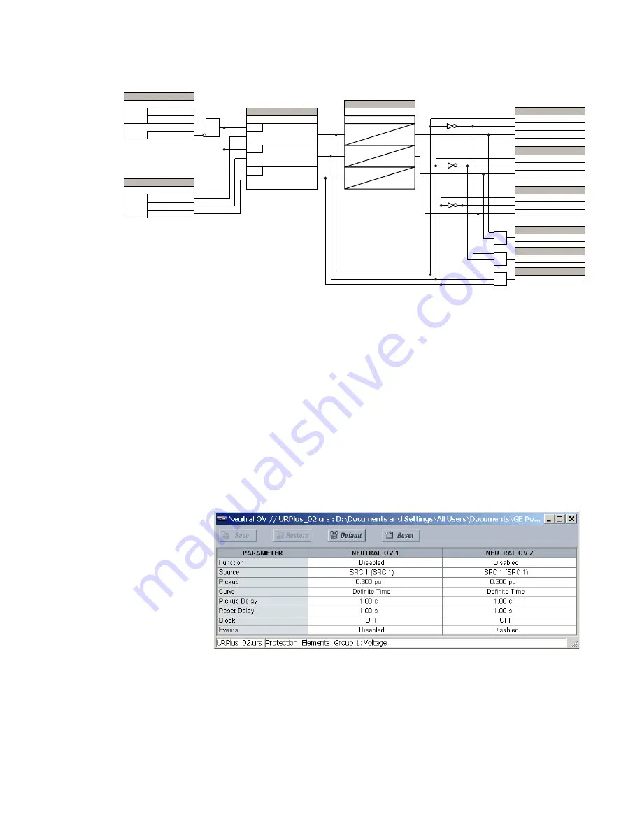
to open the neutral overvoltage configuration window.
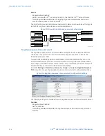
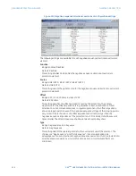
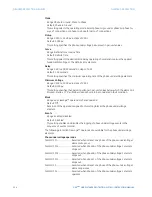
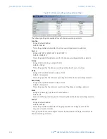
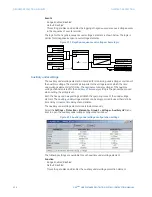
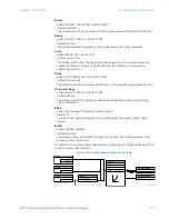
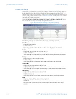
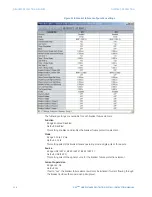
Figure 228: Neutral overvoltage configuration settings
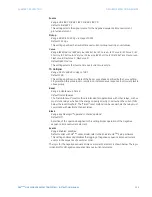
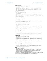
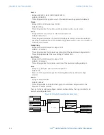
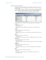
The following settings are available for each neutral overvoltage element.
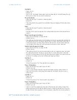
Function
Range: Enabled, Disabled
Default: Disabled
This setting enables and disables the neutral overvoltage protection element.
6(77,1*
'LVDEOHG
(QDEOHG
)XQFWLRQ
$1'
2II
%ORFN
6(77,1*
9$%
9%&
6RXUFH
9&$
6(77,1*
3LFNXS
581
9$% ! 3,&.83
581
9%& ! 3,&.83
581
9&$ ! 3,&.83
6(77,1*
3LFNXS 'HOD\
5HVHW 'HOD\
7
3.3
7
567
7
3.3
7
567
7
3.3
7
567
)/(;/2*,& 23(5$1'6
3+$6( 29 % 3.3
3+$6( 29 % '32
3+$6( 29 % 23
)/(;/2*,& 23(5$1'6
3+$6( 29 & 3.3
3+$6( 29 & '32
3+$6( 29 & 23
)/(;/2*,& 23(5$1'6
3+$6( 29 $ 3.3
3+$6( 29 $ '32
3+$6( 29 $ 23
)/(;/2*,& 23(5$1'
3+$6( 29 23
)/(;/2*,& 23(5$1'
3+$6( 29 '32
)/(;/2*,& 23(5$1'
3+$6( 29 3.3
25
$1'
25
$&'5

