CHAPTER 10: DIGITAL FAULT RECORDER
FAULT REPORT
D90
PLUS
LINE DISTANCE PROTECTION SYSTEM – INSTRUCTION MANUAL
507
•
The fault report feature is enabled.
•
The source for the fault report is properly configured.
•
The block trigger input is not asserted.
•
A record capture is not currently in progress.
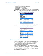
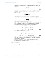
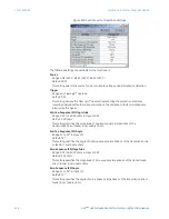
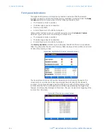
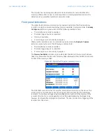
The
Memory Available
indication is green when less than 80% of the memory has been
filled. It is yellow when the amount of memory filled is between 80% and 99%, and it is red
if 100% of the memory is filled.
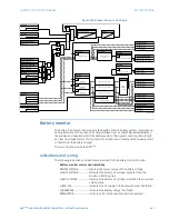
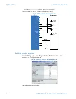
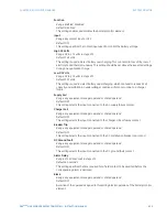
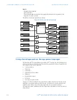
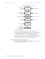
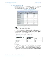
Figure 436: Digital fault reporter summary screen
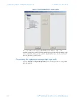
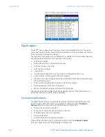
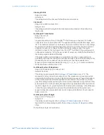
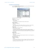
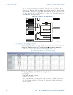
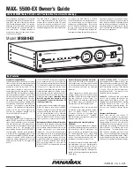
The fault report screen displays the detailed fault data for each fault This data includes the
fault and prefault current and voltage data, as well as the cause of trip, trip type, active
setting group, shot count, and duration data.
Figure 437: Fault report front panel screen
Fault report operation
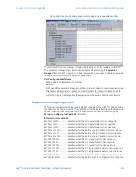
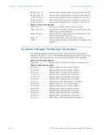
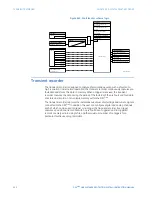
The fault report trigger can be any FlexLogic™ operand, but in most applications it is
expected to be the same operand that is used to drive an output relay to trip a breaker
(usually a virtual output). To prevent the overwriting of fault events, the disturbance
detector should not be used to trigger a fault report. A FAULT RPT TRIG event is
automatically created when the report is triggered.
If a number of protection elements are ORed to create a fault report trigger, the first
operation of any element causing the OR gate output to become high triggers a fault
report. However, If other elements operate during the fault and the first operated element
has not been reset (the OR gate output is still high), the fault report is not triggered again.
Considering the reset time of protection elements, there is very little chance that fault
report can be triggered twice in this manner.

