D90
PLUS
LINE DISTANCE PROTECTION SYSTEM – INSTRUCTION MANUAL
533
D90
Plus
Line Distance Protection System
Chapter 11: Metering
Metering
This section describes how to program the D90
Plus
metering features.
Metering source
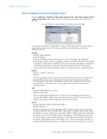
Select the
Settings > Metering > Metering Source
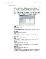
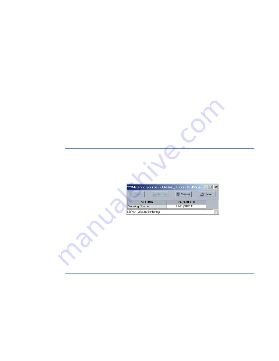
menu item to open the metering source
configuration window.
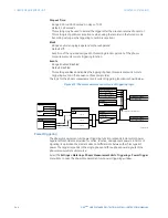
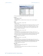
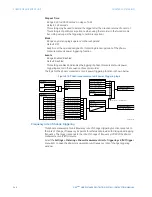
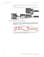
Figure 461: Metering source configuration settings
The following setting is available.
Name
Range: LINE (SRC 1), BKR 1 (SRC 2), BKR 2 (SRC 3)
Default: LINE (SRC 1)
This setting selects the source to use for calculating metered quantities available
through the front panel interface. For breaker-and-a-half schemes, select a source
which summates the current from both breakers to measure the total load on the
transmission line.
Phasor measurement unit
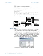
The phasor measurement unit menus allow specifying basic parameters of the
measurements process such as signal source, ID and station name, calibration data,
triggering, recording, and content for transmission on each of the supported phasor
measurement unit ports. The reporting ports menus allow specifying the content and rate
of reporting on each of the supported ports. The phasor measurement unit settings are
organized in five logical groups: basic configuration, calibration, communications,
triggering, and recording.

