540
D90
PLUS
LINE DISTANCE PROTECTION SYSTEM – INSTRUCTION MANUAL
PHASOR MEASUREMENT UNIT
CHAPTER 11: METERING
Frequency triggering
The trigger responds to the frequency signal of the phasor measurement unit source. The
frequency is calculated from either phase voltages, auxiliary voltage, phase currents and
ground current, in this hierarchy, depending on the source configuration as per
D90
Plus
standards. This element requires the frequency is above the minimum measurable
value. If the frequency is below this value, such as when the circuit is de-energized, the
trigger will drop out.
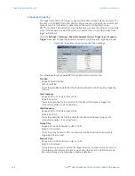
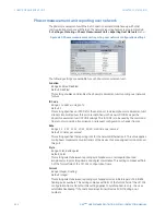
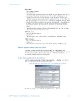
Select the
Settings > Metering > Phasor Measurement Unit > Triggering > Frequency
Trigger
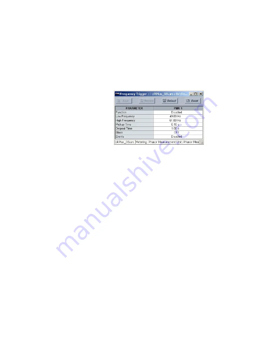
menu item to open the phasor measurement unit frequency triggering window.
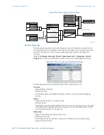
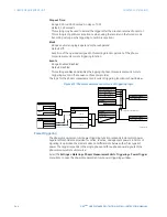
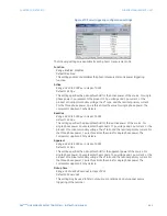
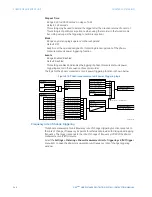
Figure 467: Frequency triggering configuration settings
The following settings are available for each phasor measurement unit.
Function
Range: Enabled, Disabled
Default: Disabled
This setting enables and disables the phasor measurement unit frequency triggering
function.
Low Frequency
Range: 20.00 to 70.00 Hz in steps of 0.01
Default: 49.00 Hz
This setting specifies the low threshold for the abnormal frequency trigger. The
comparator applies a 0.03 Hz hysteresis.
High Frequency
Range: 20.00 to 70.00 Hz in steps of 0.01
Default: 61.00 Hz
This setting specifies the high threshold for the abnormal frequency trigger. The
comparator applies a 0.03 Hz hysteresis.
Pickup Time
Range: 0.00 to 600.00 seconds in steps of 0.01
Default: 0.10 seconds
This setting may be used to filter out spurious conditions and avoid unnecessary
triggering of the recorder.
Dropout Time
Range: 0.00 to 600.00 seconds in steps of 0.01
Default: 1.00 seconds
This setting may be used to extend the trigger after the situation returned to normal.
This setting is of particular importance when using the recorder in the forced mode
(recording as long as the triggering condition is asserted).

