CHAPTER 11: METERING
PHASOR MEASUREMENT UNIT
D90
PLUS
LINE DISTANCE PROTECTION SYSTEM – INSTRUCTION MANUAL
541
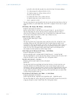
Block
Range: any metering logic operand or shared operand
Default: Off
Assertion of the operand assigned to this setting blocks operation of the phasor
measurement unit frequency triggering function.
Events
Range: Enabled, Disabled
Default: Disabled
This setting enables and disables the logging of phasor measurement unit frequency
triggering events in the sequence of events recorder.
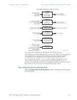
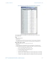
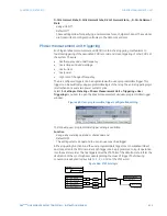
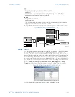
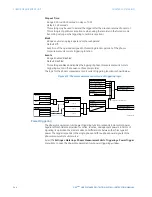
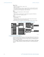
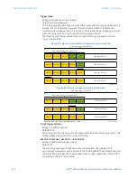
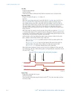
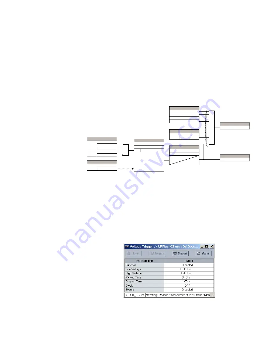
The logic for the phasor measurement unit frequency triggering function is shown below.
Figure 468: Frequency triggering scheme logic
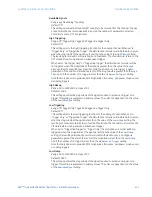
Voltage triggering
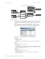
This phasor measurement unit voltage triggering function responds to abnormal voltage.
Separate thresholds are provided for low and high voltage. In terms of signaling its
operation, the element does not differentiate between the undervoltage and overvoltage
events. The trigger responds to the phase voltage signal of the phasor measurement unit
source. All voltage channels (A, B, and C or AB, BC, and CA) are processed independently
and could trigger the recorder. A minimum voltage supervision of 0.1 pu is implemented to
prevent pickup on a de-energized circuit, similarly to the undervoltage protection element.
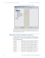
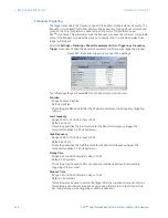
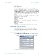
Select the
Settings > Metering > Phasor Measurement Unit > Triggering > Voltage
Trigger
menu item to open the phasor measurement unit voltage triggering window.
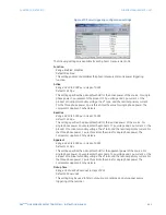
Figure 469: Voltage triggering configuration settings
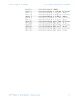
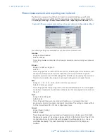
The following settings are available for each phasor measurement unit.
WR67$7ELWVRIWKHGDWDIUDPH
$&'5
6(77,1*
)UHTXHQF\
I
6RXUFH
2II
%ORFN
$1'
6(77,1*6
(QDEOHG
'LVDEOHG
)XQFWLRQ
/RZ)UHTXHQF\
25
!+LJK)UHTXHQF\
I
I
6(77,1*6
/RZ)UHTXHQF\
581
+LJK)UHTXHQF\
6(77,1*6
3LFNXS7LPH
7
3.3
7
'32
'URSRXW7LPH
)/(;/2*,&23(5$1'6
30892/775,**(5
308&85575,**(5
30832:(575,**(5
30852&2)75,**(5
6(77,1*
2II
8VHU7ULJJHU
25
)/(;/2*,&23(5$1'
30875,**(5('
)/(;/2*,&23(5$1'
308)5(475,**(5

