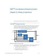

CHAPTER 15: THEORY OF OPERATION
THE D90
Plus
DISTANCE ELEMENTS
D90
PLUS
LINE DISTANCE PROTECTION SYSTEM – INSTRUCTION MANUAL
635
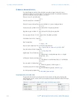
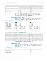
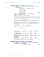
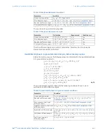
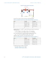
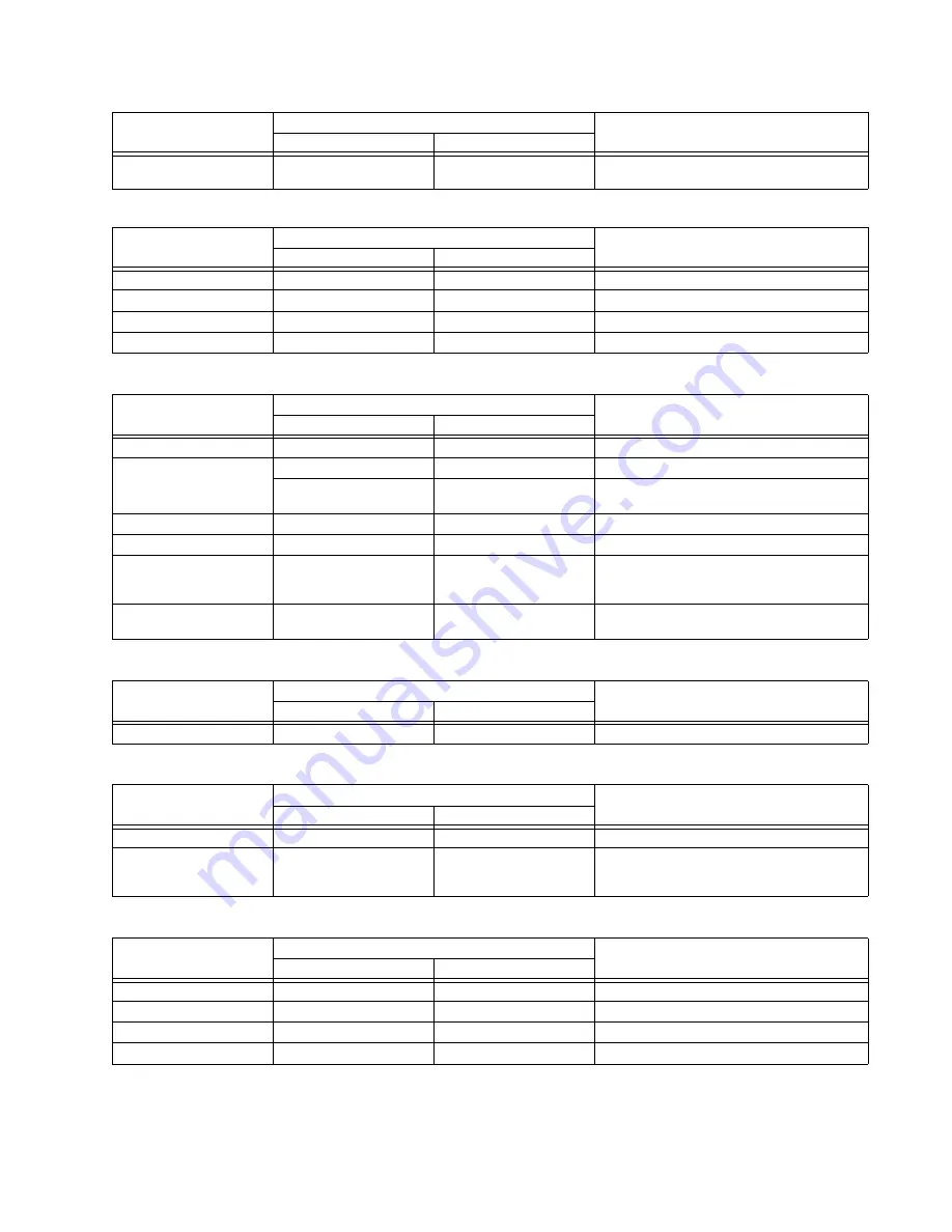
Table 15-13: Directional quadrilateral phase distance functions
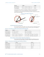
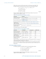
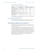
Table 15-14: Directional quadrilateral ground distance functions
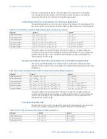
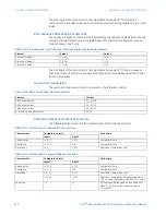
Table 15-15: Non-directional mho phase distance functions
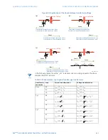
Table 15-16: Non-directional mho ground distance functions
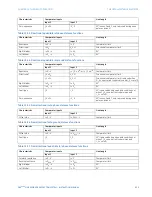
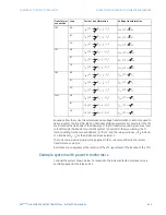
Table 15-17: Non-directional quadrilateral phase distance functions
Zero-sequence
I
_0 ×
Z
D
–
V
_0
90° (zones 2 and 3 only; removed during open
pole conditions)
Characteristic
Comparator inputs
Limit angle
Input 1
Input 2
Reactance
I
×
Z
–
V
I
×
Z
Comparator limit
Directional
I
×
Z
D
V
_1M
Directional comparator limit
Right blinder
I
×
Z
R
–
V
I
×
Z
R
90°
Left blinder
I
×
Z
L
–
V
I
×
Z
L
90°
Characteristic
Comparator inputs
Limit angle
Input 1
Input 2
Reactance
I
×
Z
–
V
j
×
I
_0 × e
j
Θ
or
j
×
I
_2 × e
j
Θ
Comparator limit
Directional
I
_0 ×
Z
D
V
_1M
Directional comparator limit
I
_2 ×
Z
D
V
_1M
Directional comparator limit (removed when
3I_0 > overcurrent supervision and I_2 < cutoff)
Right blinder
I
×
Z
R
–
V
I
×
Z
R
90°
Left blinder
I
×
Z
L
–
V
I
×
Z
L
90°
Fault type
I
_0
I
_2
50° (removed during open pole conditions or
when 3I_0 > overcurrent supervision and
I_2 < cutoff)
Zero-sequence
I
_0 ×
Z
D
–
V
_0
90° (zones 2 and 3 only; removed during open
pole conditions)
Characteristic
Comparator inputs
Limit angle
Input 1
Input 2
Offset mho
I
×
Z
–
V
I
×
Z
REV
–
V
Comparator limit
Characteristic
Comparator inputs
Limit angle
Input 1
Input 2
Offset mho
I
×
Z
–
V
I
×
Z
REV
–
V
Comparator limit
Fault type
I
_0
I
_2
50° (removed during open pole conditions or
when 3I_0 > overcurrent supervision and
I_2 < cutoff)
Characteristic
Comparator inputs
Limit angle
Input 1
Input 2
Forward reactance
I
×
Z
–
V
I
×
Z
Comparator limit
Reverse reactance
I
×
Z
REV
–
V
I
×
Z
REV
Comparator limit
Right blinder
I
×
Z
R
–
V
I
×
Z
R
90°
Left blinder
I
×
Z
L
–
V
I
×
Z
L
90°
Characteristic
Comparator inputs
Limit angle
Input 1
Input 2