
638
D90
PLUS
LINE DISTANCE PROTECTION SYSTEM – INSTRUCTION MANUAL
THE D90
Plus
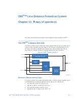
DISTANCE ELEMENTS
CHAPTER 15: THEORY OF OPERATION
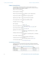
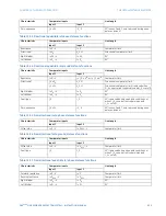
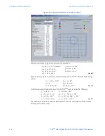
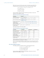
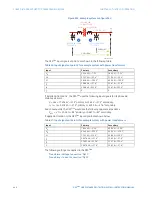
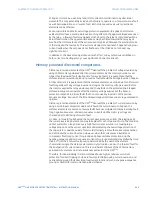
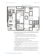
Figure 550: Typical ground distance settings window
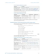
Assume the following signals are injected into the D90
Plus
.
Eq. 69
Based on these signals and the programmed settings, the D90
Plus
calculates the following
values.
Eq. 70
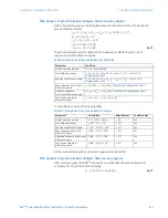
From the assumed steady-state injection, the D90
Plus
also calculates the following.
Eq. 71
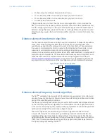
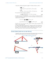
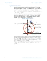
The following sub-sections describe the operation of each of the distance characteristics
with respect to these values.
9
$
9SUHIDXOW
9
$
9²
9
%
9²
9
&
9
,
$
$²
,
%
$
,
&
$²
.
0
.
B ²
=
ű
=
'
ű
=
5
ű
=
/
ű
9
$
B 9²
9
$
B0 9
,
B $²
,
$
B $²
²
9²
9
²
B 9²
9
$
9
%
²
B0 9²
9
$
9
%
,
,
$
²
$²
%