CHAPTER 6: COMMUNICATIONS
NETWORK SETTINGS
D90
PLUS
LINE DISTANCE PROTECTION SYSTEM – INSTRUCTION MANUAL
99
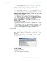
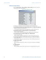
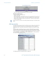
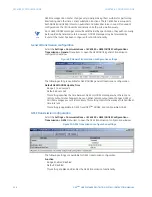
Configure IP Network Status
Range: OK, PORT 1 NETMASK ERROR, PORT 2 NETMASK ERROR, PORT 3 NETMASK ERROR,
PORT 1 IP ADDR RSVD, PORT 2 IP ADDR RSVD, PORT 3 IP ADDR RSVD, PORT 1 IP ADDR
LPBK, PORT 2 IP ADDR LPBK, PORT 3 IP ADDR LPBK, PORT 1 IP ADDR NETWK, PORT 2 IP
ADDR NETWK, PORT 3 IP ADDR NETWK, PRT 1-2 SUBNET OVRLP, PRT 1-3 SUBNET OVRLP,
PRT 2-3 SUBNET OVRLP, > 1 GATEWAY DEFINED
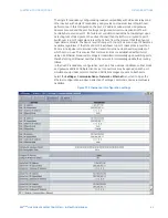
This actual value indicates the validity of the IP parameters applied to the network stack.
For details on the status values, see
on page 90. The Ethernet parameters
for ports 2 and 3 exist only when the D90
Plus
contains a communications card.
Remaining TCP/IP connections actual values
Select the
Actual Values > Communications > Remaining Connection
menu item to open
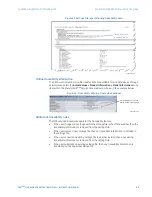
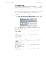
the remaining TCP/IP connections actual values window.
Figure 80: Remaining TCP/IP connections actual values
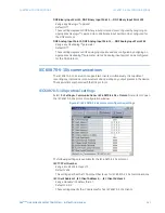
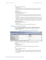
The following actual values are available to display the remaining TCP/IP connections.
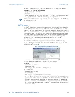
MMS Available TCP/IP Connections
Range: 0, 1, 2, 3, 4, 5
This actual value indicates the number of connections available for IEC 61850 MMS
communications.
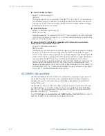
Modbus Available TCP/IP Connections
Range: 0, 1, 2, 3, 4
This actual value indicates the number of connections available for Modbus
communications.
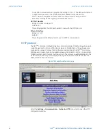
DNP Available TCP/IP Connections
Range: 0, 1, 2
This actual value indicates the number of connections available for DNP
communications. The number of DNP connections is zero unless the “Network - TCP”
value has been selected for both the
DNP Channel 1 Port
and
DNP Channel 2 Port
settings.
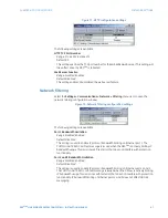
PMU Available TCP/IP Connections
Range: 0, 1
This actual value indicates the number of connections available for the phasor
measurement unit.
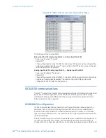
IEC Available TCP/IP Connections
Range: 0, 1, 2
This actual value indicates the number of connections available for IEC 60870-5-104
communications.

