102
D90
PLUS
LINE DISTANCE PROTECTION SYSTEM – INSTRUCTION MANUAL
DNP COMMUNICATIONS
CHAPTER 6: COMMUNICATIONS
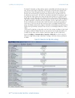
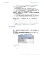
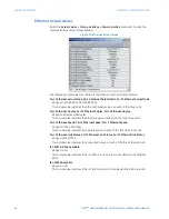
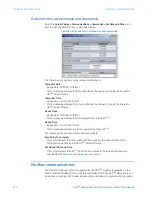
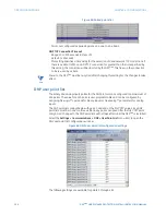
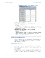
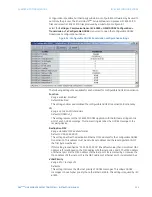
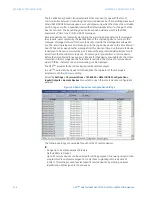
Figure 83: Modbus user map configuration settings
The following Modbus user map settings are available for each of the 256 registers.
Modbus Type
Range: None, Settings, Actuals
Default: None
This setting indicates if the Modbus user map address represents a setting or an actual
value.
Parameter
Range: Modbus memory map address in decimal representation
Default: 0
This setting represents the value of the programmed Modbus memory map address.
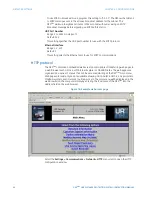
DNP communications
The DNP protocol allows for the optimization of control and data acquisition between the
equipment in the substation and the central control center. The protocol is scalable; that is,
it is designed to be compatible with the latest high speed LAN technology yet still be
implemented over slower speed serial links.
The DNP protocol improves upon many master-slave protocols by improving overall
communication performance requirements and provides time-stamping with millisecond
accuracy.
See the D90
Plus
Communications Guide for additional details on the DNP protocol.
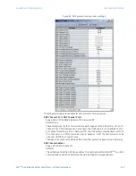
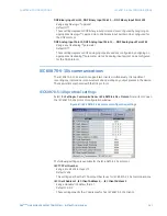
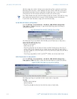
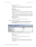
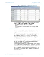
DNP protocol
The DNP server can simultaneously support one client over serial RS485 and one client
over Ethernet or two clients over Ethernet. Level 3 is supported for parsing requests and
generating responses. It is capable of reporting any indication or measurement and
operating any output present in the device. Both direct-operate and select-before-operate
modes of control are supported. Two user-configurable input and output maps are
implemented.
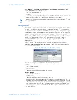
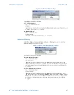
Select the
Settings > Communications > DNP > Protocol
menu item to open the DNP
protocol configuration window.


