130
D90
PLUS
LINE DISTANCE PROTECTION SYSTEM – INSTRUCTION MANUAL
IEC 61850 COMMUNICATIONS
CHAPTER 6: COMMUNICATIONS
•
Direct control with normal security.
•
SBO control with normal security.
Configuration settings are available to select the control model for each point. Each
protection virtual input used through GGIO2 should be enabled and the corresponding
SPSCO ctlModel setting programmed to the appropriate control configuration.
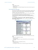
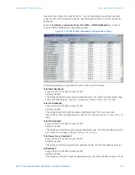
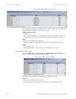
Select the
Settings > Communications > IEC 61850 > GGIO2 Control Configuration
menu
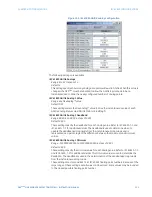
item to open the GGIO2 control configuration window.
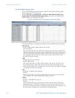
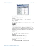
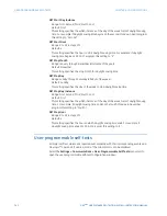
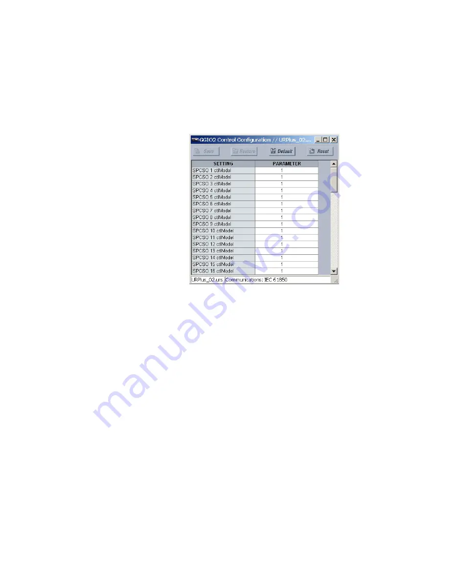
Figure 104: IEC 61850 GGIO2 control configuration
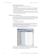
The following setting is available for each of the 64 GGIO2 control points. Each control
point is mapped to a corresponding D90
Plus
protection virtual input. For example, GGIO2
control point SPCSO 3 is mapped to protection virtual input 3.
SPCSO 1 ctlModel
Range: 0, 1, 2
Default: 1
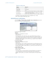
The GGIO2 control configuration settings are used to set the control model for each
input. The available choices are “0” (status only), “1” (direct control), and “2” (SBO with
normal security).
GGIO4 analog configuration
The GGIO4 logical node provides access to as many as 32 analog value points, as well as
associated timestamps and quality flags. The data content must be configured before the
data can be used. GGIO4 provides analog values for access by clients.
It is intended that clients use GGIO4 to access generic analog values from the D90
Plus
.
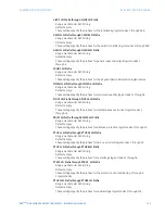
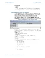
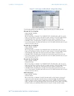
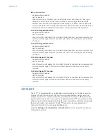
Configuration settings select the number of analog values available in GGIO4 (4 to 32) as
well as FlexAnalog™ values that determine the value of the GGIO4 analog inputs. Clients
can utilize polling or the IEC 61850 unbuffered reporting feature available from GGIO4 to
obtain the analog values provided by GGIO4.
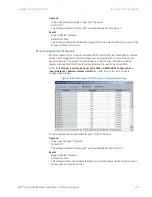
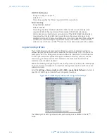
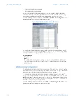
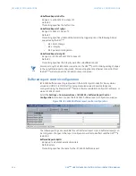
Select the
Settings > Communications > IEC 61850 > GGIO4 Analog Configuration
menu
item to open the GGIO4 analog configuration window.

