

CHAPTER 7: PROTECTION
POWER SYSTEM
D90
PLUS
LINE DISTANCE PROTECTION SYSTEM – INSTRUCTION MANUAL
169
supervise the comparator. The BLOCK input is used as one of the inputs to RUN
control.
•
Events
setting: This setting is used to control whether the pickup, dropout or operate
states are recorded by the event recorder. When set to “Disabled”, element pickup,
dropout or operate are not recorded as events. When set to “Enabled”, events are
created as follows:
–
<Element> PKP
(pickup)
–
<Element> DPO
(dropout)
–
<Element> OP
(operate)
The dropout event is created when the measure and decide comparator output
transits from the pickup state (logic 1) to the dropout state (logic 0). This could happen
when the element is in the operate state if the reset delay time is not zero.
Power system
The following section describes settings relevant to the D90
Plus
power system.
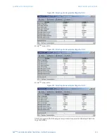
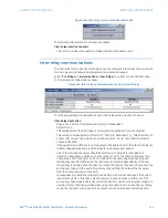
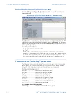
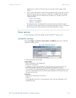
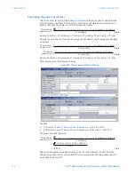
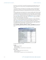
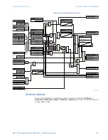
Installation settings
Select the
Settings > Protection > Power System > Installation
menu item to open the
installation settings window.
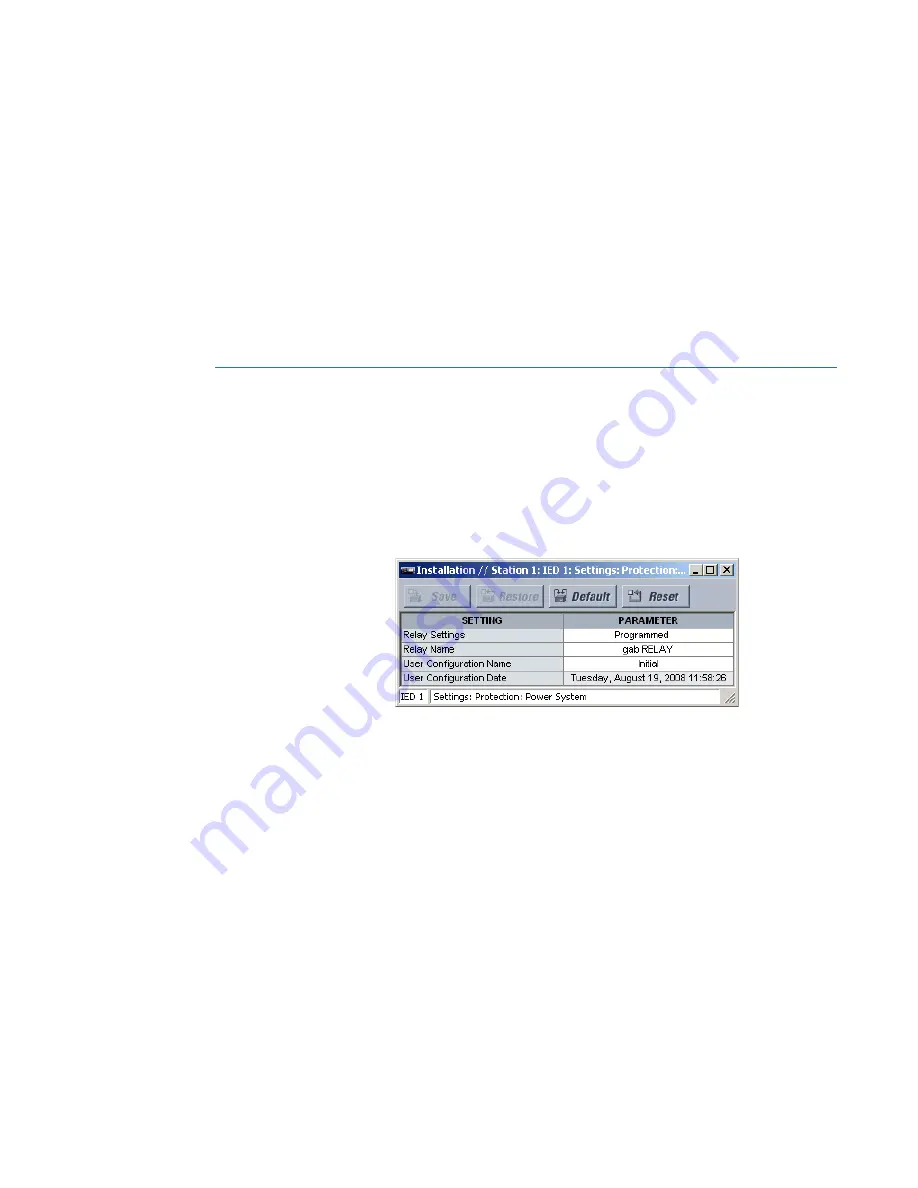
Figure 149: Installation settings
The following settings are available.
Relay Settings
Range: Programmed, Not Programmed
Default: Not Programmed
To safeguard against the installation of a device without any entered settings, the
D90
Plus
will not allow signaling of any output relay until this setting value is
“Programmed”. This setting is defaulted to “Not Programmed” when at the factory. The
UNIT NOT PROGRAMMED
self-test error message is displayed until the relay is put into
the programmed state.
Relay Name
Range: up to 20 alphanumeric characters
Default: -----
This setting allows the user to uniquely identify a relay. This name will appear on all
generated reports.


