


CHAPTER 7: PROTECTION
GROUPED PROTECTION ELEMENTS
D90
PLUS
LINE DISTANCE PROTECTION SYSTEM – INSTRUCTION MANUAL
179
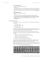
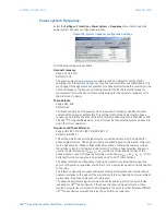
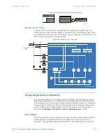
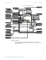
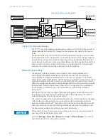
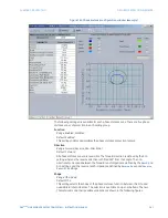
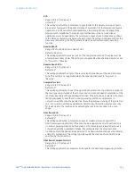
Figure 157: Disturbance detector logic scheme
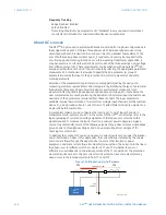
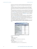
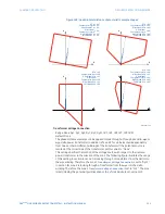
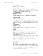
Example use of sources
Consider a D90
Plus
connected as shown below. This configuration could be used on a
transmission line connected into a breaker-and-a-half system. The following figure shows
the arrangement of sources used to provide the functions required in this application, and
the AC module inputs used to provide the data.
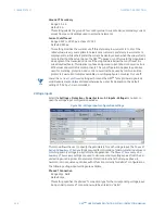
Figure 158: Example use of sources
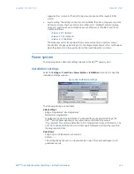
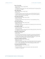
Grouped protection elements
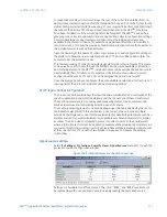
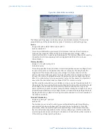
Each protection element can be assigned up to six different sets of settings according to
setting group designations 1 to 6. The performance of these elements is defined by the
active setting group at a given time. Multiple setting groups allow the user to conveniently
change protection settings for different operating situations (for example, altered power
system configuration or season of the year). The active setting group can be preset or
selected via the
Settings > Protection > Control > Setting Groups
menu item.
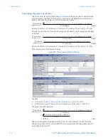
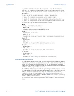
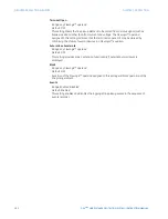
Line pickup
The line pickup feature uses a combination of undercurrent and undervoltage to identify a
line that has been de-energized (line end open). Alternately, the user may assign a
FlexLogic™ operand that specifies the terminal status. Three instantaneous overcurrent
$&'5
25
$&78$/9$/8(
,B
6RXUFH
&XUUHQW3KDVRU
,B
,B
6(77,1*
_,B_²_,B_ !îFXWRII
ŏ
&XUUHQW&XWRII/HYHO
_,B_²_,B_ !îFXWRII
ŏ
_,B_²_,B_ !îFXWRII
ŏ
ZKHUH_,B_
DUHWZRF\FOHVROG
ŏ
ŏ
ŏ
_,B_ DQG_,B_
)/(;/2*,&23(5$1'
65&''23
$&'5
$&PRGXOH
EDQN
%)
%)
3
*
$
9
:
9DU
6RXUFH
6RXUFH
9ROWV
$PSV
-
-
-
6RXUFH
853OXVVHULHV,('
$PSV
9ROWV
9ROWV
$PSV
3+
3+
3+
-
-


