186
D90
PLUS
LINE DISTANCE PROTECTION SYSTEM – INSTRUCTION MANUAL
GROUPED PROTECTION ELEMENTS
CHAPTER 7: PROTECTION
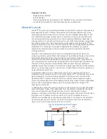
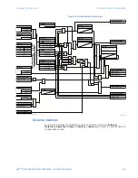
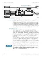
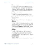
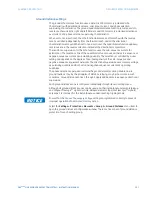
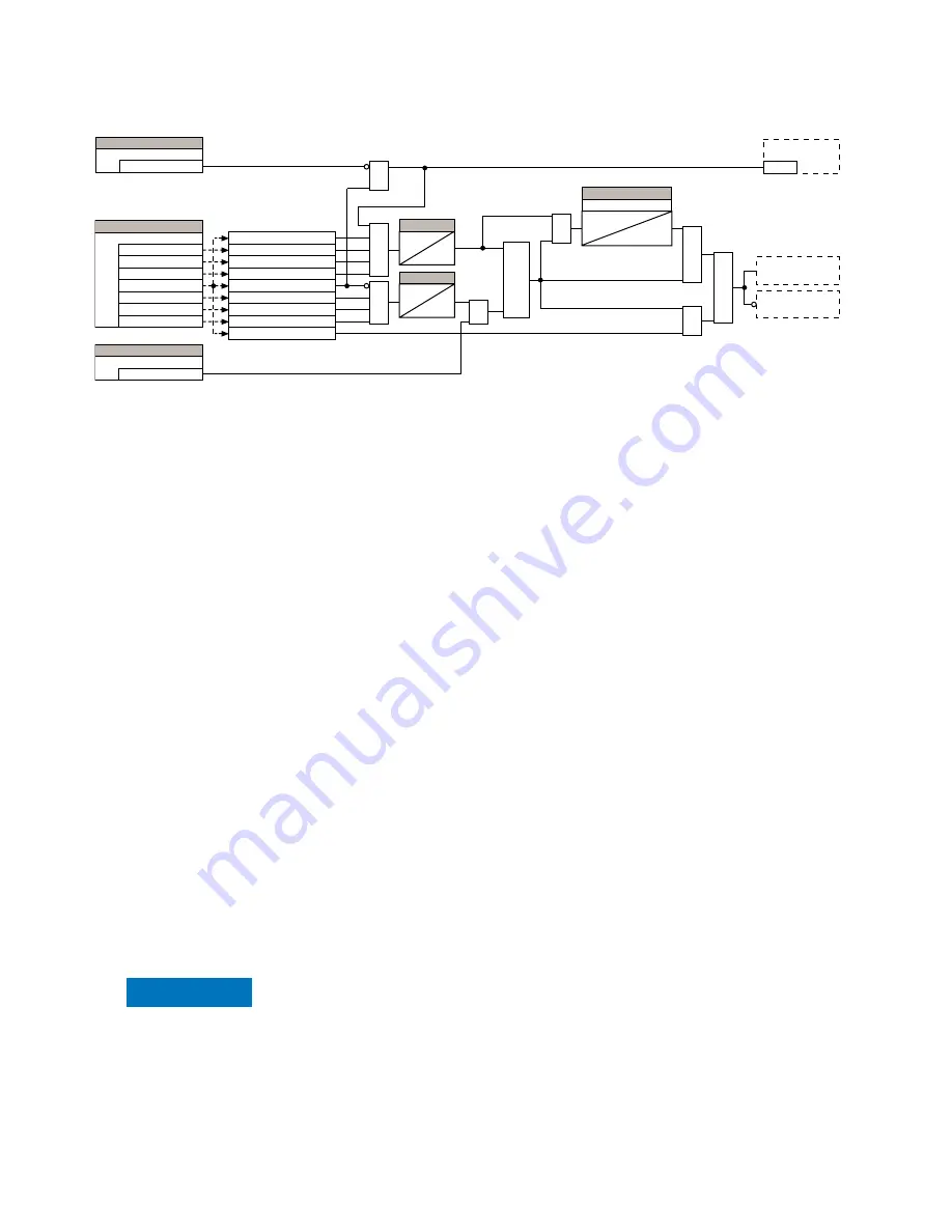
Figure 162: Memory voltage logic
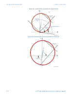
Impact of memory polarization
The D90
Plus
uses a memorized positive sequence voltage as a polarizing signal in order to
achieve dependable operation for forward faults and secure non-operation for reverse
faults.
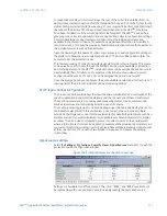
The dynamic shift of the characteristic ensures improved directionality, but it also means
that if a backup function is required for a reverse fault on the bus, then it is appropriate to
reverse zone 4 so that a time delayed backup function may be obtained. As mentioned
earlier, it may be beneficial to also avoid extremely large reach settings by setting a remote
backup so that it is reverse looking. This strategy can be beneficial if the reduced reach
enhances the discrimination between the load and fault conditions.
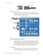
Phase distance settings
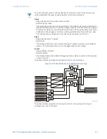
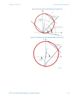
The phase mho distance function uses a dynamic 100% memory-polarized mho
characteristic with additional reactance, directional, and overcurrent supervising
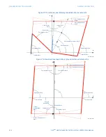
characteristics. The phase quadrilateral distance function is comprised of a reactance
characteristic, right and left blinders, and 100% memory-polarized directional and current
supervising characteristics. When set as non-directional, the mho function becomes an
offset mho with the reverse reach controlled independently from the forward reach, and all
the directional characteristics removed. When set to non-directional, the quadrilateral
function applies a reactance line in the reverse direction instead of the directional
comparators.
Each phase distance zone is configured individually through its own setting menu. All of
the settings can be independently modified for each of the zones except the common
distance settings specified in the previous section.
The common distance settings must be properly chosen for correct operation of the phase
distance elements. Although all zones can be used as either instantaneous elements
(pickup and dropout FlexLogic™ operands) or time-delayed elements (operate FlexLogic™
operands), only zone 1 is intended for the instantaneous under-reaching tripping mode.
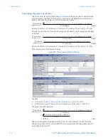
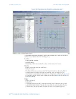
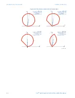
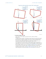
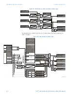
The phase distance element operating curves are shown below.
NOTICE
FASTPATH:
Ensure that the
Phase VT Secondary Voltage
setting is set correctly to prevent improper
operation of the associated memory action.
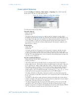
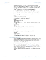
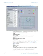
Select the
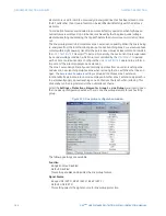
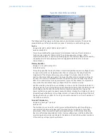
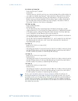
Settings > Protection > Elements > Group 1 > Phase Distance
menu item to
open the phase distance configuration window.
$&'5
8VH9B
8VH9BPHP
25
$1'
$1'
581
8SGDWHPHPRU\
'LVWDQFH6RXUFH
6(77,1*
9B$9B506B$
9B%9B506B%
9B&9B506B&
9B
,$
,%
,&
)RUFH0HPRU\3RODUL]DWLRQ
6(77,1*
2II
_9B506²_9__9B506
_9B_!SX
_9B506²_9__9B506
_9B506²_9__9B506
_9B_SX
_,%_SX
_,$_SX
_,&_SX
_9B_SX
)RUFH6HOI3RODUL]DWLRQ
6(77,1*
2II
7567
6(77,1*
0HPRU\'XUDWLRQ
4
$1'
F\FOHV
7,0(5
6
5
$1'
$1'
$1'
25
F\FOHV
7,0(5

