206
D90
PLUS
LINE DISTANCE PROTECTION SYSTEM – INSTRUCTION MANUAL
GROUPED PROTECTION ELEMENTS
CHAPTER 7: PROTECTION
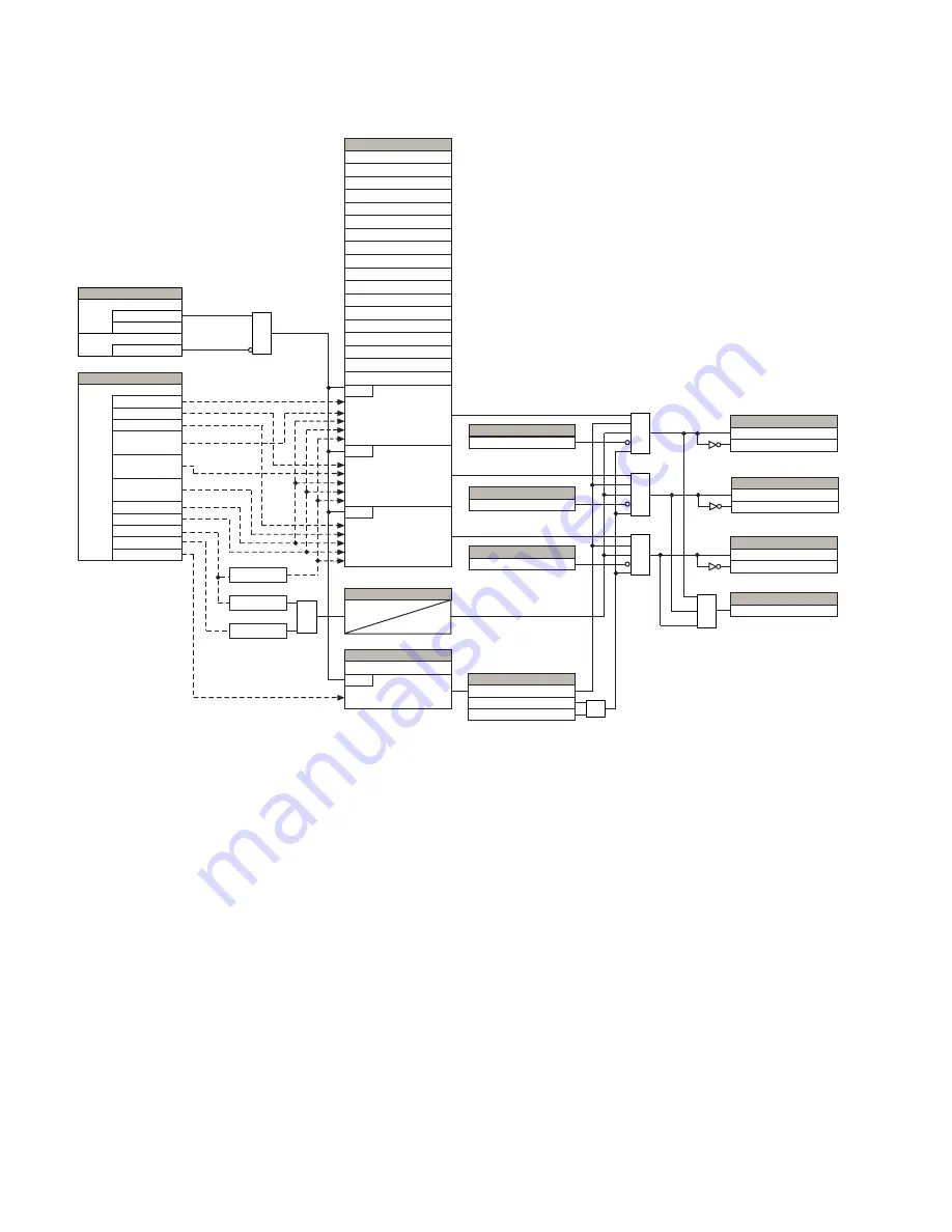
Figure 182: Ground distance zone 2 scheme logic
Ground directional supervision
A dual (zero-sequence and negative-sequence) memory-polarized directional supervision
applied to the ground distance protection elements has been shown to give good
directional integrity. However, a reverse double-line-to-ground fault can lead to a
maloperation of the ground element in a sound phase if the zone reach setting is increased
to cover high resistance faults.
Ground distance zones 2 through 5 use an additional ground directional supervision to
enhance directional integrity. The ground distance directional characteristic angle is used
as a maximum torque angle together with a 90° limit angle.
The supervision is biased toward operation in order to avoid compromising the sensitivity
of ground distance elements at low signal levels. Otherwise, the reverse fault condition
that generates concern will have high polarizing levels so that a correct reverse fault
decision can be reliably made. The supervision for zones 2, 3, and 5 is removed during
open pole conditions.
1 cycle
1 cycle
870055A4.CDR
AND
AND
AND
OR
AND
OR
Memory
V_1 > 0.80 pu
I_1 > 0.025 pu
Source
SETTING
IA
IC
IB
VAG
VBG
VCG
I_2
I_0
Direction
SETTINGS
Shape
Reach
RCA
Reverse Reach
Reverse Reach RCA
Polarizing Current
Non-Homogeneous Angle
Quadrilateral Right Blinder RCA
Quadrilateral Left Blinder
Quadrilateral Left Blinder RCA
RUN
RUN
A ELEMENT
RUN
B ELEMENT
C ELEMENT
OPEN POLE BLK A
FLEXLOGIC OPERAND
OPEN POLE BLK C
FLEXLOGIC OPERAND
Supervision
SETTING
RUN
| IN – 0.05 × I_1 | Pickup
≥
GND DIST Z2 SUPN IN
FLEXLOGIC OPERANDS
OPEN POLE BLK B
FLEXLOGIC OPERAND
GND DIST Z1 PKP B
FLEXLOGIC OPERANDS
GND DIST Z1 PKP A
FLEXLOGIC OPERANDS
GND DIST Z1 DPO A
GND DIST Z1 DPO B
GND DIST Z1 PKP C
FLEXLOGIC OPERANDS
GND DIST Z1 DPO C
GND DIST Z1 PKP
FLEXLOGIC OPERAND
SETTING
= Enabled
= Disabled
Function
= Off
Block
TIMER
V_1
I_1
IN
Z0/Z1 Magnitude
Z0/Z1 Angle
Z0M/Z1 Magnitude
Z0M/Z1 Angle
Comparator Limit
Quadrilateral Right Blinder
Voltage Level
GND DIST Z2 DIR SUPN
OPEN POLE OP
OR


