


CHAPTER 7: PROTECTION
CONTROL ELEMENTS
D90
PLUS
LINE DISTANCE PROTECTION SYSTEM – INSTRUCTION MANUAL
315
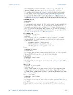
For proper operation of the scheme the zone 1 and 2 phase and ground distance elements
must be enabled, configured, and set per the standard rules of distance relaying.
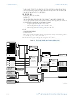
The scheme generates an output operand (
PUTT TX
) that is used to transmit the signal to
the remote end. Choices of communications channel include remote inputs and outputs
and telecommunications interfaces. When used with telecommunications facilities the
output operand should be assigned to operate an output contact connected to key the
transmitter at the interface.
The
Pickup Delay
timer setting can be used to ride through spurious PLC receive signals.
The scheme output operand (
PUTT OP
) must be configured to interface with other
D90
Plus
functions (output contacts in particular) to make the scheme fully operational.
Typically, the output operand should be programmed to initiate a trip, breaker fail, and
autoreclose, and drive a user-programmable LED as per user requirements.
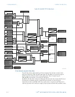
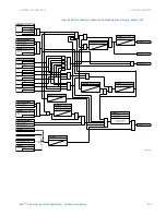
Permissive overreaching transfer trip (POTT) application guidelines
The permissive overreaching transfer trip (POTT) scheme is intended for two-terminal line
applications only. It uses an overreaching zone 2 distance element to essentially compare
the direction to a fault at both the ends of the line.
Ground directional overcurrent functions available in the D90
Plus
can be used in
conjunction with the zone 2 distance element to key the POTT scheme and initiate its
operation. This provides increased coverage for high-resistance faults.
Good directional integrity is the key requirement for an overreaching forward-looking
protection element used to supplement zone 2. Even though any FlexLogic™ operand
could be used for this purpose—allowing the user to combine responses of various
protection elements or apply extra conditions through FlexLogic™ equations—this extra
signal is primarily meant to be the output operand from either the negative-sequence
directional overcurrent element or neutral directional overcurrent element. Both of these
elements have separate forward (FWD) and reverse (REV) output operands. The forward
indication should be used (via the
NEG SEQ DIR OC1 FWD
or
NEUTRAL DIR OC1 FWD
operands).
An important consideration occurs when one of the line terminals is open. In this case, it is
necessary to identify the line terminal open condition and arrange for a continuous
sending of the permissive signal or use a slower but more secure echo feature to send a
signal to the other terminal that is producing the fault infeed. However, with any echo
scheme, a means must be provided to avoid a permanent lock up of the transmit/receive
loop. The echo duration timer (via the
Echo Duration
setting) and echo lockout timer (via
the
Echo Lockout
setting) perform this function by ensuring that the permissive signal is
echoed once for a guaranteed duration of time before going to a lockout for a user-
specified length of time.
It should be recognized that in ring bus or breaker-and-a-half situations, it may be the line
disconnect or a combination of the disconnect status, the breaker status, or both, that is
the indication that the terminal is open.
The timer specified by the
RX Pickup Delay
setting is included in the permissive receive path
to ride through spurious receive outputs that may be produced during external faults when
power line carrier is utilized as the communications medium.
No current reversal logic is included for the overreaching phase and ground distance
elements, because long reaches are not usually required for two-terminal lines. However, a
situation can occur where the ground distance element will have an extended reach. This
situation is encountered when it is desired to account for the zero-sequence inter-circuit
mutual coupling. This is not a problem for the ground distance elements in the
D90
Plus
which have current reversal logic built into their design as part of the technique
used to improve ground fault directionality.


