
378
D90
PLUS
LINE DISTANCE PROTECTION SYSTEM – INSTRUCTION MANUAL
CONTROL ELEMENTS
CHAPTER 7: PROTECTION
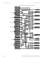
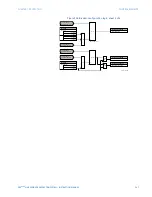
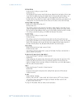
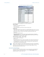
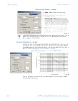
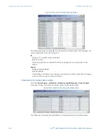
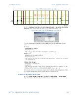
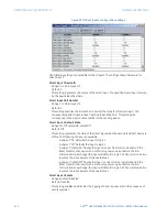
Figure 315: FlexCurve configuration settings
The following settings are available for each custom FlexCurve™.
FlexCurve Name
Range: up to 20 alphanumeric characters
Default: FlexCurve A
This setting specifies a user-defined name for the FlexCurve™.
Initialize From
Range: IEEE Moderately Inverse, IEEE Very Inverse, IEEE Extremely Inverse, IEC Curve A, IEC
Curve B, IEC Curve C, IEC Short Inverse, IAC Extreme Inv, IAC Very Inverse, IAC Inverse, IAC
Short Inverse, I Squared T, Recloser Curve, FlexCurve A, FlexCurve B, FlexCurve C,
FlexCurve D
Default: IEEE Moderately Inverse
This setting specifies a curve to use as a base for a custom FlexCurve™. When the
Initialize FlexCurve
button is clicked, the pickup settings will be populated with values
specified by the curve selected in this setting.
0.00 × Pickup, 0.05 × Pickup,..., 20.00 × Pickup
Range: 0 to 65535 ms in steps of 1
Default: 0 ms
These settings specify the time to reset and operate at the following pickup levels: 0.00
to 0.98 and 1.03 to 20.00. This data is converted into two continuous curves by linear
interpolation between data points. To enter a custom FlexCurve™, enter the reset or
operate time for each selected pickup point.
NOTE
NOTE:
Special care must be applied when setting the two points that are close to the multiple of
pickup of 1; that is, 0.98 pu and 1.03 pu. It is recommended to set the two times to a similar
value; otherwise, the linear approximation may result in undesired behavior for the
operating quantity that is close to 1.00 pu.
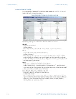
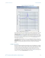
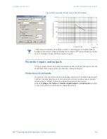
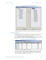
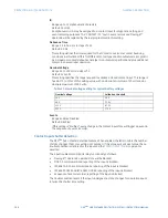
FlexCurve™ software features
The EnerVista UR
Plus
Setup software allows for easy configuration and management of
FlexCurves™ and their associated data points. Click on the
View FlexCurve
button to
graphically display the selected FlexCurve™.