394
D90
PLUS
LINE DISTANCE PROTECTION SYSTEM – INSTRUCTION MANUAL
PROTECTION INPUTS AND OUTPUTS
CHAPTER 7: PROTECTION
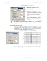
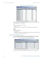
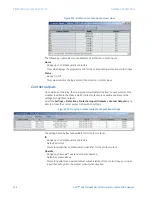
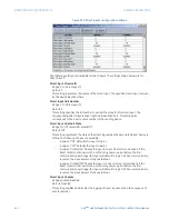
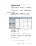
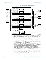
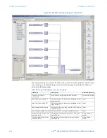
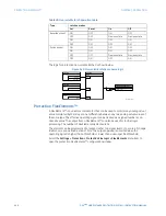
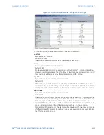
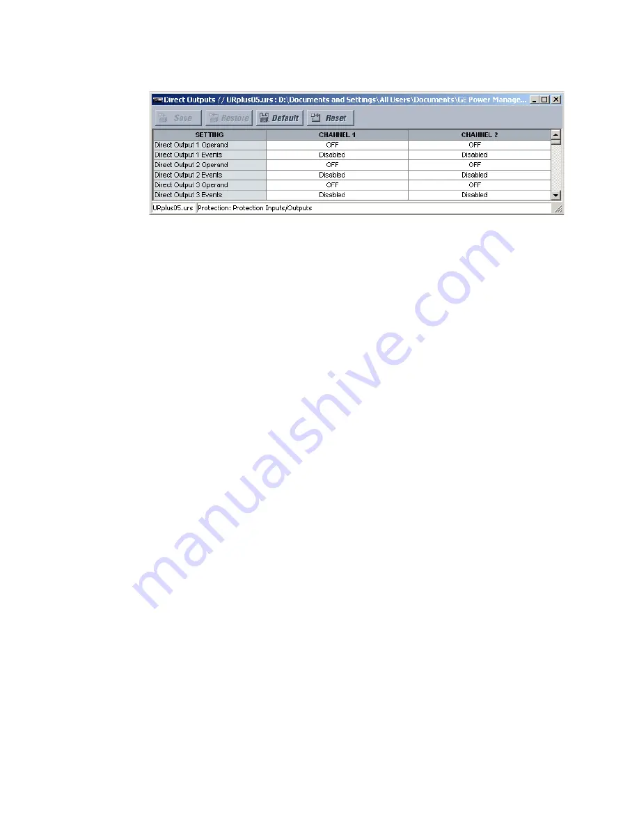
Figure 336: Direct output configuration settings
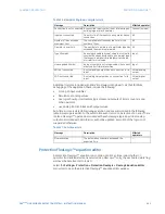
The following settings are available for all direct outputs. The default values shown
correspond to direct output 1.
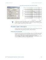
Direct Input 1 Operand
Range: any FlexLogic™ operand
Default: Off
This setting specifies the FlexLogic™ operand that determines the state of the direct
output.
Direct Input 1 Events
Range: Enabled, Disabled
Default: Disabled
This setting enables and disables the logging of direct output events in the sequence of
events recorder.
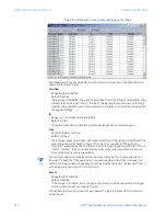
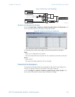
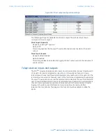
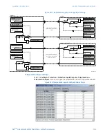
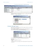
Teleprotection inputs and outputs
The D90
Plus
provides 16 teleprotection inputs on communications channel 1 (numbered 1-
1 through 1-16) and 16 teleprotection inputs on communications channel 2 (on two-
terminals two-channel and three-terminal systems only, numbered 2-1 through 2-16). The
remote relay connected to channels 1 and 2 of the local relay is programmed by assigning
FlexLogic™ operands to be sent via the selected communications channel. This allows the
user to create distributed protection and control schemes via dedicated communications
channels. Some examples are directional comparison pilot schemes and direct transfer
tripping. It should be noted that failures of communications channels will affect
teleprotection functionality. The teleprotection function must be enabled to utilize the
inputs.


