

450
D90
PLUS
LINE DISTANCE PROTECTION SYSTEM – INSTRUCTION MANUAL
AUTOMATION CONTROL
CHAPTER 8: AUTOMATION
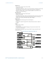
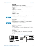
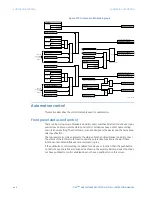
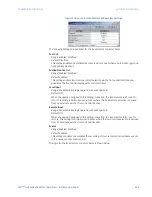
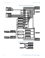
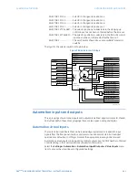
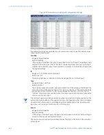
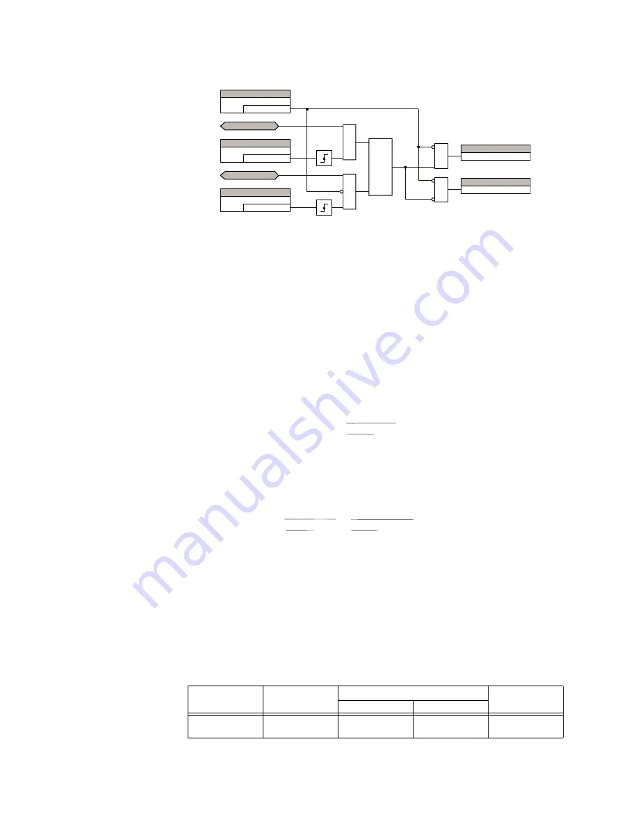
Figure 379: Local-remote control scheme logic
Synchrocheck
The are two identical synchrocheck elements available, numbered 1 and 2.
The synchrocheck (synchronism check) function is intended for supervising the paralleling
of two parts of a system which are to be joined by the closure of a circuit breaker. The
synchrocheck elements are typically used at locations where the two parts of the system
are interconnected through at least one other point in the system.
Synchrocheck verifies that the voltages (
V
1
and
V
2
) on the two sides of the supervised
circuit breaker are within set limits of magnitude, angle and frequency differences. The
time that the two voltages remain within the admissible angle difference is determined by
the setting of the phase angle difference
∆Φ
and the frequency difference
∆
F
(slip
frequency). It can be defined as the time it would take the voltage phasor
V
1
or
V
2
to
traverse an angle equal to 2 ×
∆Φ
at a frequency equal to the frequency difference
∆
F
. This
time can be calculated by:
Eq. 42
In this equation,
∆Φ
represents the phase angle difference in degrees and
∆
F
represents
the frequency difference in hertz.
For example, for default values of
∆Φ
= 30° and
∆
F
= 0.1 Hz, the time the angle between the
two voltages will be less than the set value is:
Eq. 43
If one or both sources are de-energized, the synchrocheck programming can allow for
closing of the circuit breaker using undervoltage control to bypass the synchrocheck
measurements (via the dead source function).
Using the synchrocheck function
The selected sources for synchrocheck inputs
V
1
and
V
2
(which must not be the same
source) may include both a three-phase and an auxiliary voltage. The relay will
automatically select the specific voltages to be used by the synchrocheck element in
accordance with the following table.
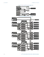
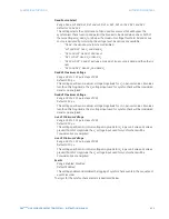
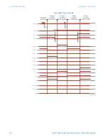
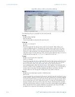
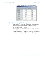
Table 30: Voltages used by the synchrocheck element
25
$&'5
6(77,1*
(QDEOHG
)XQFWLRQ
)URQWSDQHO/2&$/
6(77,1*
2II
/RFDO,QSXW
25
)URQWSDQHO5(027(
6(77,1*
2II
5HPRWH,QSXW
/DWFK
6
5
5HVHWGRPLQDQW
25
25
)/(;/2*,&23(5$1'
/5/21
)/(;/2*,&23(5$1'
/5521
7
ŝ
)
î
î
ŝ
Ǝ
7
î
ŝ
)
î
î
+]
î
VHF
ŝŮ
V
1
or
V
2
(source
Y
)
V
2
or
V
1
(source
Z
) Auto-selected combination
Auto-selected
voltage
Source
Y
Source
Z
Phase VTs and
auxiliary VT
Phase VTs and
auxiliary VT
Phase
Phase
V
AB


