588
D90
PLUS
LINE DISTANCE PROTECTION SYSTEM – INSTRUCTION MANUAL
MIMIC DIAGRAM EDITOR
CHAPTER 12: LOCAL INTERFACE
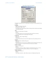
Display in Line
Range: 1, 2, 3
Default: 1
This setting specifies the line in the annunciator alarm to display the metered value. It
can be displayed in lines 1, 2, or 3 if the page layout is 3 × 4 or 4 × 6. For 6 × 8 layouts, it
can be displayed in lines 1 or 2.
Mimic diagram editor
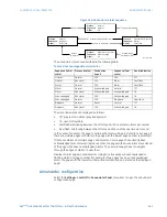
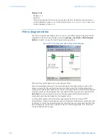
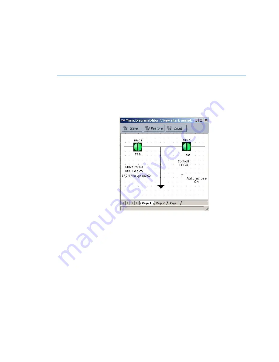
The mimic diagram editor allows users to create customized single line diagrams (mimic
diagrams) for the front panel display. Select the
Settings > Local HMI > Mimic Diagram
Editor
menu item to open the mimic diagram editing window.
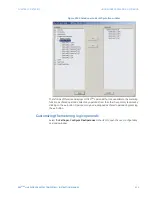
Figure 511: Mimic diagram editor with example diagram
There are 1 top level pages in the mimic diagram editor.
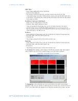
Each top level diagram has up to ten sub-level diagrams corresponding to each of the
active components. The sub-level diagram is rendered when the corresponding active
component is selected for operation. To create a sub-level diagram, first select the breaker
or switch instance in the diagram editor then right-click the mouse button and select the
GoTo SLD
item. A new diagram is created and populated with the selected active
component and a new tab added to the diagram editor.
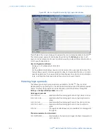
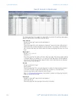
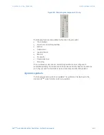
A components library is included on the upper-right side of the EnerVista UR
Plus
Setup software. These include dynamic power components, static power components, and
text blocks. To create the single line diagram, select the desired component and then click
the drawing pane to place the component. Once on the drawing plane, the component
can be positioned accordingly.


