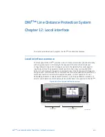


CHAPTER 12: LOCAL INTERFACE
MIMIC DIAGRAM EDITOR
D90
PLUS
LINE DISTANCE PROTECTION SYSTEM – INSTRUCTION MANUAL
589
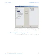
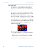
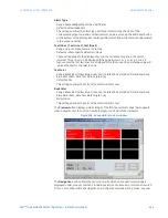
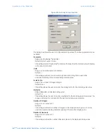
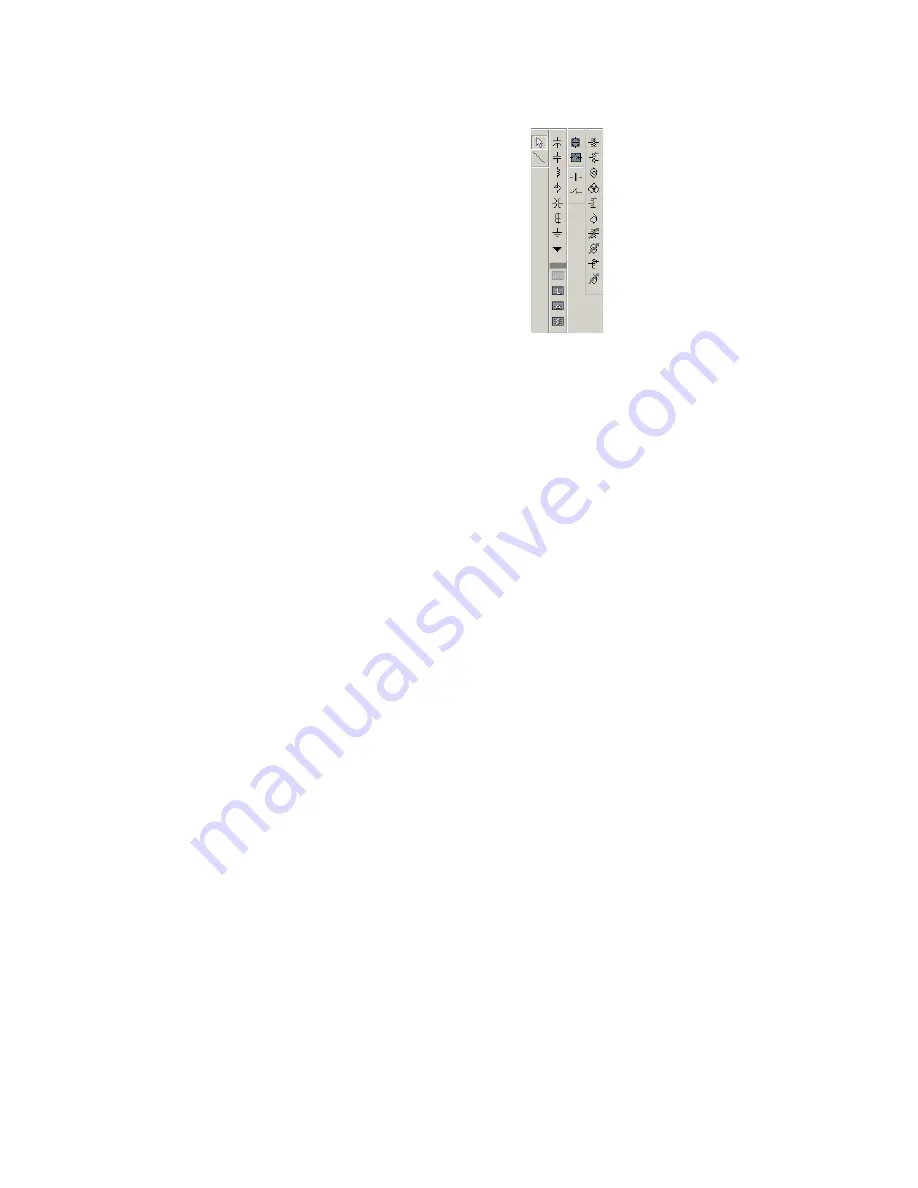
Figure 512: Mimic diagram components library
The following functions are available for the mimic diagram editor.
•
Circuit breakers.
•
Disconnect and earthing switches.
•
Busbars.
•
Transformers.
•
Capacitor banks.
•
Reactors.
•
CTs and VTs.
•
Transmission lines.
•
Grounding.
The circuit breakers, disconnects, and earthing switches can be configured to
automatically display the actual status of these devices. All other devices are static. As
such, they are used for information only and cannot dynamically change states.
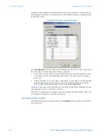
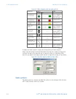
Dynamic symbols
The following dynamic symbols are available. The symbols can be displayed in the
standard UR
Plus
-series format or as IEC style symbols.


