


CHAPTER 12: LOCAL INTERFACE
MIMIC DIAGRAM EDITOR
D90
PLUS
LINE DISTANCE PROTECTION SYSTEM – INSTRUCTION MANUAL
593
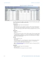
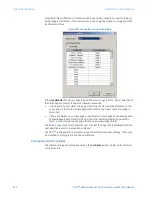
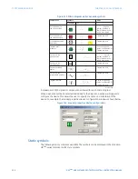
Scale Factor
Range: G (Giga), M (Mega), k (kilo), None
Default: None
This setting allows the user to select a scaling factor for the metering units value. The
range is restricted to correspond to the selected analog value parameter.
Multiplier
Range: dependent on the selected analog value
Default: None
This setting allows the user to specify the multiplier for the metering units value if the
scaling factor is set to “None”.
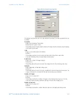
Number of Integers
Range: 1 to 12 in steps of 1
Default: 1
This setting selects the number of integer places displayed for the metering block.
Number of Decimals
Range: 0 to 10 in steps of 1
Default: 3
This setting selects the number of decimal places displayed for the metering block.
Text Color
Range: available system colors
Default: Black
This setting specifies the displayed text color for the metering block.
Font Size
Range: 8, 10, 12
Default: 8
This setting specifies the displayed font size for the metering block.
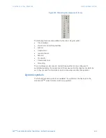
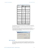
Text blocks
Text blocks are used to display various control quantities. These text blocks allow the user
to display specified control states in the configurable mimic diagram. The three types of
text blocks available are shown below. A maximum of three text blocks can be used per
mimic diagram.
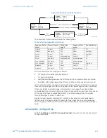
Figure 519: Mimic diagram text block symbols
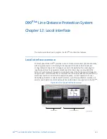
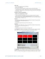
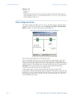
View modes
The mimic diagram editor has three viewing modes: edit mode, overview mode, and
control mode. These modes are toggled via the three mode buttons on menu bar.
The edit mode is used when creating and modifying mimic diagrams with the editor.
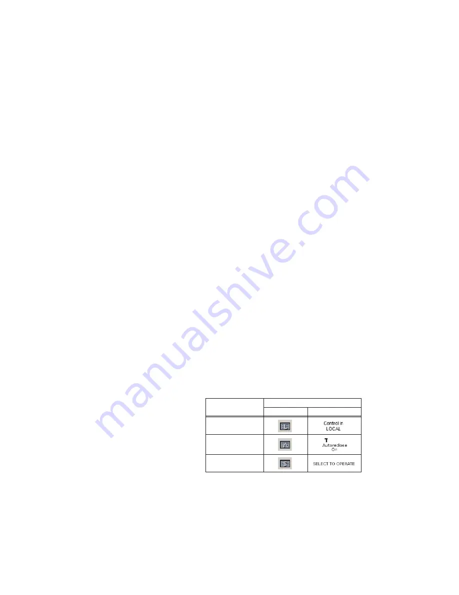
,QWHUIDFH V\PEROV
7H[W EORFN W\SH
%XWWRQ
([DPSOH GLVSOD\
/RFDOUHPRWH WH[W
EORFN
$XWRUHFORVH WH[W
EORFN
6HOHFWWRRSHUDWH
WH[W EORFN
$&'5