7 Troubleshooting
M1046983 04/08
7-29
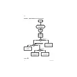
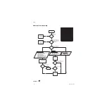
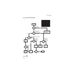
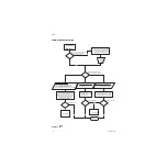
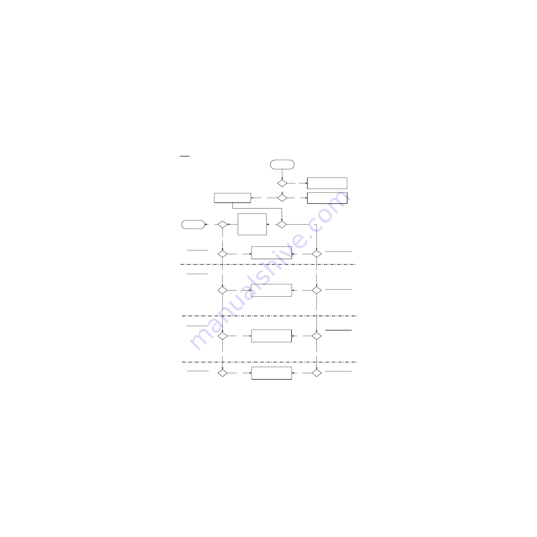
7.7 System Troubleshooting Flowcharts
Flowchart
6
AB.91.013
Start
Turn on System
Review Active Alarms, Error
Log and Alarm Log.
Proceed to "Display
Troubleshooting”
Yes
No
Does the System Application
Screen Appear?
Are there Alarms
relating to the
event?
Troubleshoot
Error/Alarm Logs
and Users Reference
Manual URM (Part 2)
Yes
Yes
Diagnosis
Achieved?
No
Proceed to "Breathing System
Leak Troubleshooting”
Proceed to "Inaccurate Volume
Ventilation Troubleshooting”
Proceed to "No Ventilation
Troubleshooting”
Yes
Yes
Yes
Yes
Yes
Yes
No
No
No
No
Proceed to "High Intrinsic
PEEP Troubleshooting”
Yes
Yes
No
No
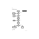
Alarms
Alarms of Type:
Breathing system loose
Circuit Leak
System Leak
Alarms of Type:
Calibrate flow sensors
Calibrate, Dry, or replace -
Flow Sensors
Check flow sensors
Replace insp / exp flow -
sensor
Reverse insp / exp Flow
Tv not achieved
System Leak
Unable to Drive Bellows
Volume sensors disagree
Alarms of Type:
Apnea; Apnea > 120s
No Fresh Gas Flow!
Unable to Drive Bellows
Ventilate Manually
Ventilator has no Drive Gas
Vol vent only. No PEEP or -
PSV
Ppeak Low. Leak?
Alarms of Type:
Inspiration Stopped
Negative airway pressure
PEEP High. Blockage?
Ppeak high
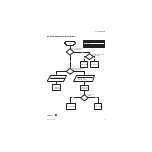
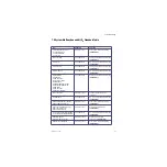
Symptoms of Type:
Continuously High Peep
during operation
Symptoms
Symptoms of Type:
No Pressure Waveform
No Flow Waveform
No Bellows Movement
Symptoms of Type:
Set T
V
vs. Measured T
V
Symptoms of Type:
Bellows Falls
Leak detected
No
Did System go to
Alt O2 or System
Malfunction?
Proceed to “Alt O2 / System
Malfunction Troubleshooting”
Yes
No
Problem Solved
Legend:
ACB = Anesthesia Control Board
PCB = Power Controller Board
VIB = Ventilator Interface Board
DU = Display Unit
GIV = Gas Inlet Valve
APL = Adjustable Pressure Limit
AB.75.070
Summary of Contents for Datex-Ohmeda Aisys Carestation
Page 1: ...Aisys Anesthesia Machine Technical Reference Manual ...
Page 16: ...Notes xiv 04 08 M1046983 ...
Page 32: ...Notes 1 16 04 08 M1046983 ...
Page 158: ...Notes 5 20 04 08 M1046983 ...
Page 288: ...Notes 7 106 04 08 M1046983 ...
Page 325: ...9 Repair Procedures M1046983 04 08 9 29 The rear inverter A B C ...
Page 356: ...Notes 9 60 04 08 M1046983 ...
Page 401: ...10 Illustrated Parts M1046983 04 08 10 45 14 1 2 3 6 5 4 5 8 7 15 16 18 17 10 9 11 12 13 or ...
Page 452: ...Notes 10 96 04 08 M1046983 ...
Page 466: ...11 14 04 08 M1046983 Notes ...
Page 470: ...Aisys 12 4 04 08 M1046983 12 3 System Schematics 12 3 1 Power Schematic ...
Page 478: ...Aisys 12 12 04 08 M1046983 12 6 3 Tools Transfer Logs ...
Page 497: ......

