Aisys
7-30
04/08 M1046983
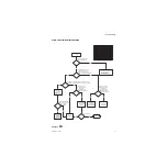
Display Troubleshooting
Flowchart
7
AB.91.013
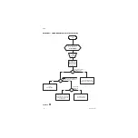
Start
Turn on System
Check Contrast
Adjustment in
Screen Set-up
No
Yes
Check / Replace
Backlight tubes,
cables, and
inverters
Replace the DU
CPU board
Use Flashlight to
Illuminate Display.
Can information be
seen?
Problem
continues?
Yes
No
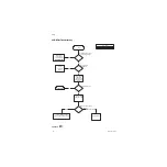
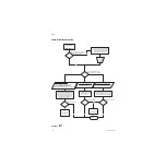
Problem
continues?
No
Yes
Boot-up with
System Download
Card
Does Display
boot normally?
Check power to ACB
Yes
No
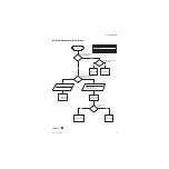
Check for DU
12.5v; On PCB J3
Pin 4 - 15
Is 12.5v within
Limit(12.5
±
0.18V)?
Yes
Replace the DU
CPU Board
No
Check for On/Standby
Switch signal; On PCB
J4 Pin 2 - 10
Measured Voltage
> 2.5v in Standby
state and < 1.3v in
ON state?
Yes
Replace the PCB
No
Check On/Standby
• Switch Connections
• Operation
• Associated harness connections
Troubleshoot Power
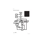
Problem
Download New / All
Yes
No
Is 12.5v from
PCB “OK”?
Problem Solved
Is the Green Power Indicator
on Dashboard illuminated?
Yes
No
Ensure Mains Power is
connected. If connected,
Troubleshoot the Power
Inlet problem.
Does the Screen display the
company logo or any information?
AB.75.071
Summary of Contents for Datex-Ohmeda Aisys Carestation
Page 1: ...Aisys Anesthesia Machine Technical Reference Manual ...
Page 16: ...Notes xiv 04 08 M1046983 ...
Page 32: ...Notes 1 16 04 08 M1046983 ...
Page 158: ...Notes 5 20 04 08 M1046983 ...
Page 288: ...Notes 7 106 04 08 M1046983 ...
Page 325: ...9 Repair Procedures M1046983 04 08 9 29 The rear inverter A B C ...
Page 356: ...Notes 9 60 04 08 M1046983 ...
Page 401: ...10 Illustrated Parts M1046983 04 08 10 45 14 1 2 3 6 5 4 5 8 7 15 16 18 17 10 9 11 12 13 or ...
Page 452: ...Notes 10 96 04 08 M1046983 ...
Page 466: ...11 14 04 08 M1046983 Notes ...
Page 470: ...Aisys 12 4 04 08 M1046983 12 3 System Schematics 12 3 1 Power Schematic ...
Page 478: ...Aisys 12 12 04 08 M1046983 12 6 3 Tools Transfer Logs ...
Page 497: ......


