Aisys
7-70
04/08 M1046983
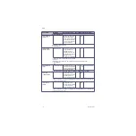
PCB Saved Alarm On:
DU to PSC Comm
Error
Indicates a the Power
Controller to Display Unit
communication was lost.
The Power Controller
“saved” the error and
communicated the error to
the Display Unit when
communication was next
established.
PCB
No Service Action Required.
PCB Saved Error:
POWER CNTRL COM
FAIL
Indicates communication
between the Display Unit
computer and the
Anesthesia Controller Board
(ACB) was lost and a Power
Controller error occurred.
The error was stored until
communication could be re-
established and written to
the Display Unit computer.
PCB
Check the Anesthesia Controller Board (ACB) to Display Unit communication cable.
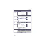
PCSELF TEST
Internal failure. System
may shut down
PC failed self tests (memory,
voltages, or CPU).
High
PC
Reboot system. If problem continues, check power supplies in the Service Software.
Replace Power Controller Board if continues.
PEEP PCV NOT
AVAILABLE
Vol vent only. No PEEP
or PSV
Paw data is in range but the
Pmanifold <= -15 cmH
2
O
Medium
Or Low
DC
None
Perform flow sensor calibration. If calibration fails, use the Service Application Vent diagnostics to check
the transducer precision. Use the Flow valve control to compare linearity of the Manifold transducer to
the Paw transducer.
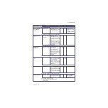
PORT ZERO READ BACK
FAIL
Read back of a latch storing
valve state did not match the
commanded state of the
valves indicating internal
Agent Delivery Board failure.
EV
Replace ADB.
(Also see Section 7.10.)
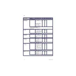
POWER CONTROLER
COM FAIL
Internal failure. System
may shut down
Communications with PC and
DC cannot be established for
ten seconds.
Medium
DC
Reboot system. If problem continues:
1. Check DU cable connections.
2. Check the Display Connector board cable connections.
3. Replace the Power Controller board.
Error Log Entry
Alarm Text
Condition (Basic info)
Priority Source Enabling Criteria
Action/Troubleshooting
Summary of Contents for Datex-Ohmeda Aisys Carestation
Page 1: ...Aisys Anesthesia Machine Technical Reference Manual ...
Page 16: ...Notes xiv 04 08 M1046983 ...
Page 32: ...Notes 1 16 04 08 M1046983 ...
Page 158: ...Notes 5 20 04 08 M1046983 ...
Page 288: ...Notes 7 106 04 08 M1046983 ...
Page 325: ...9 Repair Procedures M1046983 04 08 9 29 The rear inverter A B C ...
Page 356: ...Notes 9 60 04 08 M1046983 ...
Page 401: ...10 Illustrated Parts M1046983 04 08 10 45 14 1 2 3 6 5 4 5 8 7 15 16 18 17 10 9 11 12 13 or ...
Page 452: ...Notes 10 96 04 08 M1046983 ...
Page 466: ...11 14 04 08 M1046983 Notes ...
Page 470: ...Aisys 12 4 04 08 M1046983 12 3 System Schematics 12 3 1 Power Schematic ...
Page 478: ...Aisys 12 12 04 08 M1046983 12 6 3 Tools Transfer Logs ...
Page 497: ......

