9 Repair Procedures
M1046983 04/08
9-23
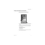
9.11 Servicing the High Performance Display Unit
Note
The item numbers appearing in parenthesis in this section refer to items in the parts list
in Section 10.41.
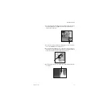
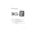
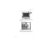
The fan filter (26) and the access door (3) to
the Compact Flash interface can be replaced
with the Display Unit in place.
To replace the filter, slide the filter capsule (25)
downward to remove it from the Display Unit.
To service other components of the Display Unit, you must first remove the Display Unit
from the machine.
9.11.1 Remove the
Display Unit
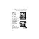
The Display Unit is mounted to the wrist assembly on the display arm. It is held in place
with four screws.
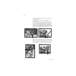
1. Disconnect the cables from the Display Unit.
2. Before removing the display, move the display arm to its highest position.
3. Remove the DU from the display arm.
• If the DU is the only display, it is mounted to a counterweight that is attached to
the wrist assembly. Remove the four screws that hold the DU to the counterweight.
• If the display arm also supports an optional monitor display, the DU is attached to
a vertical or horizontal mounting plate through four keyhole slots. Loosen the four
screws that hold the DU to the mounting plate.
(3)
(26)
(25)
Summary of Contents for Datex-Ohmeda Aisys Carestation
Page 1: ...Aisys Anesthesia Machine Technical Reference Manual ...
Page 16: ...Notes xiv 04 08 M1046983 ...
Page 32: ...Notes 1 16 04 08 M1046983 ...
Page 158: ...Notes 5 20 04 08 M1046983 ...
Page 288: ...Notes 7 106 04 08 M1046983 ...
Page 325: ...9 Repair Procedures M1046983 04 08 9 29 The rear inverter A B C ...
Page 356: ...Notes 9 60 04 08 M1046983 ...
Page 401: ...10 Illustrated Parts M1046983 04 08 10 45 14 1 2 3 6 5 4 5 8 7 15 16 18 17 10 9 11 12 13 or ...
Page 452: ...Notes 10 96 04 08 M1046983 ...
Page 466: ...11 14 04 08 M1046983 Notes ...
Page 470: ...Aisys 12 4 04 08 M1046983 12 3 System Schematics 12 3 1 Power Schematic ...
Page 478: ...Aisys 12 12 04 08 M1046983 12 6 3 Tools Transfer Logs ...
Page 497: ......


