Aisys
9-42
04/08 M1046983
9.15 Service the cylinder supply modules
w
WARNING
Be careful not to expose internal components to grease or oil (except Krytox or
equivalent).
9.15.1 Tightening
procedure for
high-pressure
tube fittings
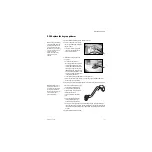
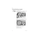
The regulator for an outboard cylinder supply is connected to the high pressure hose
assembly through a copper tube with fittings at both ends. Use the following tightening
procedure whenever you are replacing the regulator or the high pressure hose
assembly.
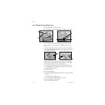
1. Insert the tubing into the fitting until the ferrule seats in the fitting.
2. Tighten the nut by hand.
3. Continue tightening the nut with a wrench until it reaches the original position (about
1/4 turn). You will feel an increase in resistance at the original position.
4. After reaching the original position, tighten the nut just slightly.
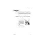
Note
If you are installing a new tube that has not been tightened before, tighten the nut with
a wrench an additional 3/4 of a turn after the nut is finger tight.
9.15.2 Replace
primary regulator
module (complete
replacement)
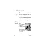
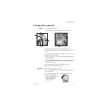
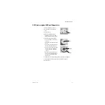
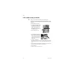
1. Bleed all gas pressure from the machine (Section 9.2).
2. Ensure that all cylinder and pipeline pressures are at zero before proceeding.
3. Remove the rear upper panels
4. Disconnect the output tube fitting (
A
).
5. Cut the cable ties (
B
) that hold the looped
cable to the transducer body.
6. Remove the three mounting screws (
C
)
and lockwashers.
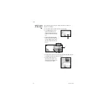
7. Remove the elbow fitting from the
replacement gas supply.
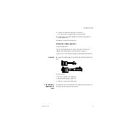
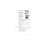
8. Transfer the pressure transducer (and
elbow fitting, if present) to the new supply
(Section 9.16).
• Remove any teflon tape remnants from
the transducer mounting threads
(transducer and module).
• Apply 1-1/4 turns of new teflon tape around the treads. Verify that the first few
threads are free of tape.
• Install the transducer.
• Replace the cable ties.
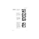
A
C
B
Summary of Contents for Datex-Ohmeda Aisys Carestation
Page 1: ...Aisys Anesthesia Machine Technical Reference Manual ...
Page 16: ...Notes xiv 04 08 M1046983 ...
Page 32: ...Notes 1 16 04 08 M1046983 ...
Page 158: ...Notes 5 20 04 08 M1046983 ...
Page 288: ...Notes 7 106 04 08 M1046983 ...
Page 325: ...9 Repair Procedures M1046983 04 08 9 29 The rear inverter A B C ...
Page 356: ...Notes 9 60 04 08 M1046983 ...
Page 401: ...10 Illustrated Parts M1046983 04 08 10 45 14 1 2 3 6 5 4 5 8 7 15 16 18 17 10 9 11 12 13 or ...
Page 452: ...Notes 10 96 04 08 M1046983 ...
Page 466: ...11 14 04 08 M1046983 Notes ...
Page 470: ...Aisys 12 4 04 08 M1046983 12 3 System Schematics 12 3 1 Power Schematic ...
Page 478: ...Aisys 12 12 04 08 M1046983 12 6 3 Tools Transfer Logs ...
Page 497: ......


