Aisys
2-14
04/08 M1046983
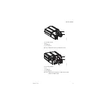
2.5 System connections
2.5.1 Display Unit
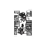
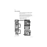
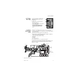
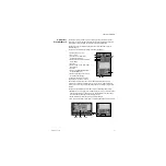
The Display Unit accommodates the following connections:
• System Power Interface (
1
).
• System Signal Interface (
2
).
• Serial Port — standard interface for external communication (
3
).
• Remote monitor On/Standby (
4
).
• Network connection — Standard Ethernet port for network connectivity (
5
).
• USB port — standard USB 2.0 interface (
6
).
• USB port — standard USB 2.0 interface (
7
).
2.5.2 Display
Connector board
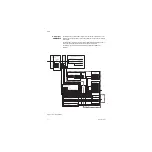
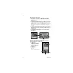
The front side of the Display Connector board accepts the following cables:
• System Power Interface to Display Unit (
1
).
• System Signal Interface to Display Unit (
2
).
• Airway Module (M-Gas) Power Supply board (
8
).
• Not used (
9
).
• The back side of the Display Connector board accepts the following cables:
• Power Controller board (
10
).
• Anesthesia Control board (MGAS power) connector (
11
).
• Anesthesia Control board (signal) connector (
12
).
• I/O to Auxiliary Connector board (
13
).
4
5
6
7
3
2
1
9
10
11
12
13
8
2
1
Summary of Contents for Datex-Ohmeda Aisys Carestation
Page 1: ...Aisys Anesthesia Machine Technical Reference Manual ...
Page 16: ...Notes xiv 04 08 M1046983 ...
Page 32: ...Notes 1 16 04 08 M1046983 ...
Page 158: ...Notes 5 20 04 08 M1046983 ...
Page 288: ...Notes 7 106 04 08 M1046983 ...
Page 325: ...9 Repair Procedures M1046983 04 08 9 29 The rear inverter A B C ...
Page 356: ...Notes 9 60 04 08 M1046983 ...
Page 401: ...10 Illustrated Parts M1046983 04 08 10 45 14 1 2 3 6 5 4 5 8 7 15 16 18 17 10 9 11 12 13 or ...
Page 452: ...Notes 10 96 04 08 M1046983 ...
Page 466: ...11 14 04 08 M1046983 Notes ...
Page 470: ...Aisys 12 4 04 08 M1046983 12 3 System Schematics 12 3 1 Power Schematic ...
Page 478: ...Aisys 12 12 04 08 M1046983 12 6 3 Tools Transfer Logs ...
Page 497: ......


