Aisys
11-10
04/08 M1046983
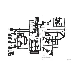
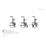
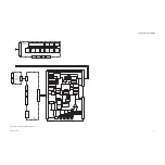
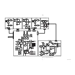
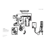
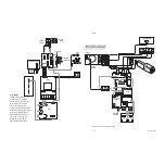
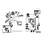
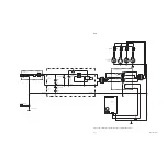
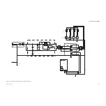
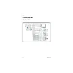
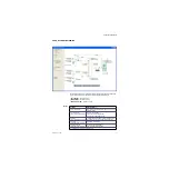
Figure 11-9 • Electrical cabling block diagram
P
P
P
P
P
P
AB.75.066
ABS/FB
Mixer
VIB
PanCB
(A) from ACB
(B) from ACB
Electronic Vaporizer
Pipeline
Supplies
Cylinder
Supplies
Alt O
2
Top - - Bottom
Cassette
AB.75.034
Key to Symbols
ABS/FB = ABS/Filter Board
ACB = Anesthesia Control Board
AuxCB = Auxiliary Connector Board
DCB = Display Connector Board
DIS = Device Interface Solution
F-CU8 = Central Unit, 8 module frame
HPDU = High Performance Display Unit
M-Gas = Compact Airway Module
MGAS/PS = MGAS Power Supply
PanCB = Pan Connector Board
PCB = Power Controller Board
VIB = Ventilator Interface Board
M-GAS
HPDU
F-CU8*
PCB
ACB
12 VDC
12 VDC
Power Supply
(U-Frame)
(A) to PanCB
(B) to PanCB
MGAS/PS
+
+
–
–
AuxCB
From
Toroid
Note*
:
The Central Unit (F-CU8) must be
Rev 10 or greater to use battery backup.
Battery
Backup
12 inch AM Display
DIS
Summary of Contents for Datex-Ohmeda Aisys Carestation
Page 1: ...Aisys Anesthesia Machine Technical Reference Manual ...
Page 16: ...Notes xiv 04 08 M1046983 ...
Page 32: ...Notes 1 16 04 08 M1046983 ...
Page 158: ...Notes 5 20 04 08 M1046983 ...
Page 288: ...Notes 7 106 04 08 M1046983 ...
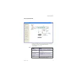
Page 325: ...9 Repair Procedures M1046983 04 08 9 29 The rear inverter A B C ...
Page 356: ...Notes 9 60 04 08 M1046983 ...
Page 401: ...10 Illustrated Parts M1046983 04 08 10 45 14 1 2 3 6 5 4 5 8 7 15 16 18 17 10 9 11 12 13 or ...
Page 452: ...Notes 10 96 04 08 M1046983 ...
Page 466: ...11 14 04 08 M1046983 Notes ...
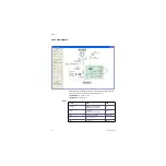
Page 470: ...Aisys 12 4 04 08 M1046983 12 3 System Schematics 12 3 1 Power Schematic ...
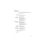
Page 478: ...Aisys 12 12 04 08 M1046983 12 6 3 Tools Transfer Logs ...
Page 497: ......


