2 Theory of Operation
M1046983 04/08
2-25
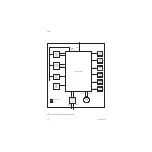
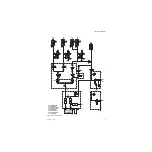
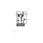
Desired gas flows are sent from the Anesthesia Control board to the Gas Mixer.
Gas Mixer operation is controlled through a microcontroller which:
• Sends requests for the Anesthesia Control board to open and close selector valves for
O
2
, N
2
O and Air.
• Regulates flow control valves for O
2
and balance gas (N
2
O or Air).
Closed-loop flow control is accomplished through a hot-wire anemometer in concert
with the flow control valves. Gas flow, based on a calibration table, is on target when
the reference measurement equals the flow measurement.
Pressure measurements across each of the flow sensor channels are used as checks
on the flow measurement for hazard mitigation, ambient pressure compensation, and
compensation for back pressure downstream of the Mixer.
In case of certain failures or errors, Alternate O
2
control activates automatically to
delivers O
2
and agent through an alternate pneumatic path to the patient circuit.
Alternate O
2
can be activated manually through a front panel control. Agent delivery
cannot be activated in case of certain Gas Mixer failures
Figure 2-20 • Electronic Gas Mixer block diagram
Flow Sensor
Assembly
350 ma max.
Balance
Gas
Vaporizer
T1 F1
T2 F2
RS422 Serial
Interface Driver
130 ma max.
Signal
Conditioning
8 Channel Analog
Mutiplexer
(BIT Signals)
Atmel AVR Mega128L
Processor with
128K Flash,
4K RAM,
4K EEPROM
12 Bit A/D
SPI Port
Watchdog
Analog
References
CODE
CPU
RCV
XMIT
VLV1
VLV2
FAIL
Diagnostic
Indicators
A
CB Board
12.5
VDC
3.3 VDC
Regulator
VDD
5.5 VDC
Regulator for
Flow Sensors
FAN Hi/Lo
Regulator
T
T
Fan
300ma
max.
Air
N2O
Alternate
O2
Valve
Drive
I2C
Port
A/D
Port
JTAG Emulator
Interface
Oxygen Valve
Drive
Balance Gas
Valve Drive
O2
Press.
Press.
Press.
AB.91.122
Summary of Contents for Datex-Ohmeda Aisys Carestation
Page 1: ...Aisys Anesthesia Machine Technical Reference Manual ...
Page 16: ...Notes xiv 04 08 M1046983 ...
Page 32: ...Notes 1 16 04 08 M1046983 ...
Page 158: ...Notes 5 20 04 08 M1046983 ...
Page 288: ...Notes 7 106 04 08 M1046983 ...
Page 325: ...9 Repair Procedures M1046983 04 08 9 29 The rear inverter A B C ...
Page 356: ...Notes 9 60 04 08 M1046983 ...
Page 401: ...10 Illustrated Parts M1046983 04 08 10 45 14 1 2 3 6 5 4 5 8 7 15 16 18 17 10 9 11 12 13 or ...
Page 452: ...Notes 10 96 04 08 M1046983 ...
Page 466: ...11 14 04 08 M1046983 Notes ...
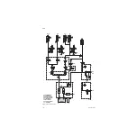
Page 470: ...Aisys 12 4 04 08 M1046983 12 3 System Schematics 12 3 1 Power Schematic ...
Page 478: ...Aisys 12 12 04 08 M1046983 12 6 3 Tools Transfer Logs ...
Page 497: ......

