9 Repair Procedures
M1046983 04/08
9-39
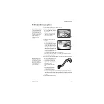
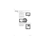
9.13.3 Replacing
GIV components
Lubricate items marked with an asterisk (
*
) sparingly with Krytox.
1. Remove the retaining ring (
A
) and the GIV cap (
B
).
2. Use pneumatic pressure to remove the shuttle. Cover the shuttle with a cloth and
briefly apply pressure (connect the drive gas hose or use pipeline pressure) through
the drive gas inlet.
3. Remove the upper o-ring (
C
) and the lower o-rings (
D
).
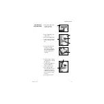
4. Install the lower o-ring (
D*
).
5. Lubricate the shuttle (
E
) at the three areas (
*
) shown: the circumference of the
shuttle where the upper and lower u-cup seals are placed and the body part of the
shuttle that slides along the lower o-ring.
6. Install the lower u-cup seal (
F*
) and the upper u-cup seal (
G*
) on the shuttle.
7. Press the shuttle assembly into the GIV manifold.
8. Install the upper o-ring (
C*
).
9. Install the cap (
B
) and the retaining ring (
A
).
10. Reassemble in reverse order.
AB.23.150
AB.23.149
A
*
*
*
AB.23.148
D*
B
E*
F*
G*
C*
Summary of Contents for Datex-Ohmeda Aisys Carestation
Page 1: ...Aisys Anesthesia Machine Technical Reference Manual ...
Page 16: ...Notes xiv 04 08 M1046983 ...
Page 32: ...Notes 1 16 04 08 M1046983 ...
Page 158: ...Notes 5 20 04 08 M1046983 ...
Page 288: ...Notes 7 106 04 08 M1046983 ...
Page 325: ...9 Repair Procedures M1046983 04 08 9 29 The rear inverter A B C ...
Page 356: ...Notes 9 60 04 08 M1046983 ...
Page 401: ...10 Illustrated Parts M1046983 04 08 10 45 14 1 2 3 6 5 4 5 8 7 15 16 18 17 10 9 11 12 13 or ...
Page 452: ...Notes 10 96 04 08 M1046983 ...
Page 466: ...11 14 04 08 M1046983 Notes ...
Page 470: ...Aisys 12 4 04 08 M1046983 12 3 System Schematics 12 3 1 Power Schematic ...
Page 478: ...Aisys 12 12 04 08 M1046983 12 6 3 Tools Transfer Logs ...
Page 497: ......


