*(.&
DIAC / DIFC / DSFC Digital Overcurrent Protection
25
Reset And Manual Trip
Targets can be reset by depressing the front
cover target reset button for the DIFC or lifting
the target reset level at the lower left edge of the
cover on the DIAC and DSFC.
Trip Circuit Test
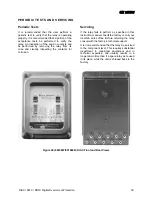
The front panel contains two manual trip levers
to test the trip circuit. The relay cover must be
removed to access the lever. The lever must be
pulled and then lifted which prevents uninten-
tional uplifted to prevent unintentional operation.
Trip Circuit
CAUTION: The trip circuit is polarity sensi-
tive. The trip circuit will not be damaged if
connected in reverse. However, it will not trip
the associated breaker. The trip circuit is
configured to have the positive battery ter-
minal connected to Stud 1 for the TOC and
IOC trip circuit and the negative to Stud 2
(TOC) and Stud 3 (IOC).
NOTE: Both trip circuits are suitable for use
with Cap-Trip devices.
Cover Installation DIAC and DSFC
NOTE: When replacing the cover on the DIAC
and DSFC relays the reset wire should be
“locked” behind the nameplate by a slight left to
right motion to place the reset wire in the correct
position.
Receiving, Handling And Storage
Immediately upon receipt, the relay should be
unpacked and examined for any damage sus-
tained during shipment. If damage occurred
during shipment a damage claim should be filed
at once with the transportation company, and the
nearest GE sales office should be notified. If the
relay is not installed immediately, it should be
stored in its original carton in a location that is
dry and protected from dust, metallic chips and
severe atmospheric conditions.
Summary of Contents for DIAC
Page 2: ......


