3.3 INSTALLATION PROCEDURE
The UPS can be used in a stand alone tower format using the two supporting stands (section 3.3.1), or
can be mounted in a 19 inch rack using the mounting brackets (section 3.3.2). Proceed with the
corresponding section, and then connect internal batteries (section 3.3.3 fro 5/6 kVA models and section
3.3.4 for 8/10 kVA models). All required items are included in the delivery, except rails – available as rail
kit option.
NOTE
The UPS output sockets are live as soon as the UPS is connected to the main
power supply, even if the UPS has not been switched on via the front panel.
3.3.1 Tower installation – preparations (all models)
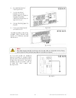
fig. 3.3.1.a
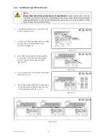
fig. 3.3.1.b
1. On 5/6 kVA models align terminals on
the backside of the PDU with UPS ones
and slide PDU in the UPS (fig. 3.3.1.a).
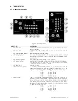
2. Assemble the plastic support stand
and place them in the desired position
(2, fig. 3.3.1.b / 3.3.1.c).
3. Place the cabinet upright in to the
plastic support stand and mount
top covers (3, fig. 3.3.1.b / 3.3.1.c).
4. Attach the display sticker (4, fig. 3.3.1.b /
3.3.1.c).
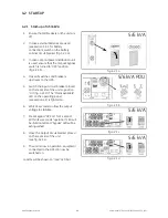
The GT Series UPS is now ready for further
connection: proceed with internal battery
connection.
fig. 3.3.1.c
5/6 kVA
5/6 kVA
8/10 kVA
modifications reserved
9
User manual GT Series 5/6/8/10 kVA UPS 1.0 (US)


