background image


2  -  Introduction


2.1 Description 

 
More than ever before, today's advanced electronic equipment, with complex integrated circuits and other 
sensitive electronics, needs a stable and continuous AC power supply to operate correctly. While the power 
coming from the wall outlet is often unreliable, a 

GE Digital Energy™ LP UPS

 provides the security of 

completely uninterrupted power. 
 
A compact, truly on-line system, the LP UPS protects your equipment from all forms of power interference, 
including complete power failure. A simple and elegant circuit design, together with extensive protection against 
abnormal operating conditions (e.g. overload, short circuit, overheating), makes the LP UPS exceptionally 
reliable. 


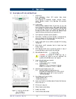
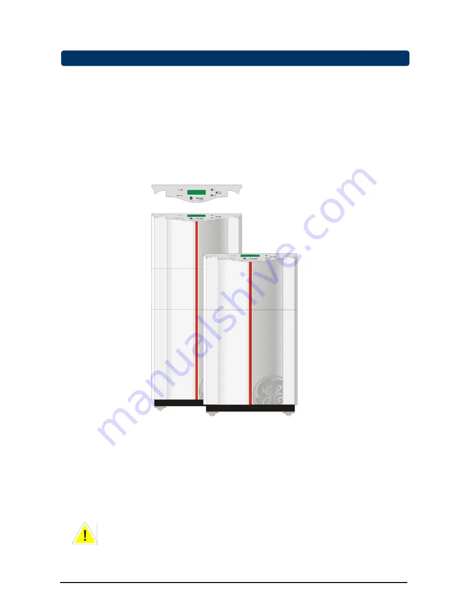
Figure 1.  The GE Digital Energy™ LP 11 UPS: 3/5/6-11 (front) and 8/10-11 (rear) 


2.2 Warranty 

 
GE Digital Energy, operating through its authorized agents, warrants that the standard products will be free of 
defects in materials and workmanship for a period of 24 months (12 months for the battery) after the date of 
invoice, or such other period as may be specified. 
 

NOTE:

 This warranty does not cover failures of the product which result from incorrect installation, 

misuse, alterations by persons other than authorized agents, or abnormal operating conditions. 


OPM_LPE_11X_3K0_10K_1GB_V041 

5


GE DE LP 11 UPS: User manual 4.1 (GB)


Summary of Contents for Digital Energy LP 11

Page 1: ...GE Consumer Industrial Power Protection OPERATING MANUAL Digital Energy LP 11 Uninterruptible Power Supply 3 5 6 8 10 kVA ...

Page 2: ...ully read the important safety instructions in chapter 1 before installation of this device 2006 by GE Industrial Systems All rights reserved The information contained in this publication is intended solely for the purposes indicated The present publication and any other documentation supplied with the UPS system is not to be reproduced either in part or in its entirety without the prior written c...

Page 3: ...4 parallel operating units additional info 5 OPERATION 16 5 1 Description of front and rear panel 5 2 Start up 5 3 Use 5 3 1 Information menu 5 3 2 Status and alarm menu 5 3 3 Service menu 5 3 4 Set up menu 5 4 Test screens 5 4 1 Battery test general 5 4 2 Quick battery test 5 4 3 Deep battery calibration test 5 5 Other features 5 5 1 Shutdown 5 5 2 Start without batteries 5 5 3 Sleep and wake up ...

Page 4: ...hen the UPS is disconnected from the utility supply Dangerous voltages may be present during battery operation The batteries must be disconnected during maintenance or service work The UPS contains potentially hazardous voltages WARNING This is a Class A UPS product In a domestic environment this product may cause radio interference in which case the user may be required to take additional measure...

Page 5: ... and service work including battery replacement should be performed by qualified service personnel When replacing the batteries use only the same type and size battery Never short circuit batteries When working with batteries remove watches rings or other metal objects and use only insulated tools Avoid charging in a sealed container Never dispose of batteries in a fire they may explode Do not ope...

Page 6: ... with extensive protection against abnormal operating conditions e g overload short circuit overheating makes the LP UPS exceptionally reliable Figure 1 The GE Digital Energy LP 11 UPS 3 5 6 11 front and 8 10 11 rear 2 2 Warranty GE Digital Energy operating through its authorized agents warrants that the standard products will be free of defects in materials and workmanship for a period of 24 mont...

Page 7: ...AINS POWER WITH DISTURBANCES Figure 2 Block diagram of the LP 11 UPS mains present 3 3 Utility Failure In the event of a utility power failure i e absent or outside tolerance the system uses the energy reserve stored in the battery to continue to produce AC power ensuring unbroken output fig 3 No interruption or alteration will ever be noticed in the output power In the event of an extended utilit...

Page 8: ... CONVERTER SYSTEM ON OFF MICROPROCESSOR CONTROL BATTERY BATTERY EXTENSION OPTIONAL RFI FILTER INPUT CONVERTER BATTERY CHARGER BYPASS FILTER Figure 4 Bypass operation automatic bypass If a power failure occurs during bypass operation load power is lost If the UPS functions under overload conditions it may not be able to protect the load 3 5 Manual Bypass Switch Service switch The system can be bypa...

Page 9: ...is present please notify the carrier and place of purchase immediately 4 4 Location Please refer to sections 1 2 and 1 3 of IMPORTANT SAFETY INSTRUCTIONS 4 5 Installation IMPORTANT Before making any connection and switching on the LP UPS please check the following conditions the voltage and frequency of your utility supply is 220 230 240 Vac and 50 60 Hz off factory the output of the UPS is set to...

Page 10: ... 17 and close the fuse holder 7 An emergency shutdown switch can be connected to connector J3 on the RS232 Contact Interface Card between pins 3 and 4 See section 6 2 for more information 8 For advanced communication possibilities the RS232 contact interface port 12a can be connected to a computer system See section 6 1 for more information 9 The middle option slot 13 allows easy installation of p...

Page 11: ...f applicable lead the DC cable through the hole on the left side of the cover Re install the cover Fasten it with 4 screws 6 In case of 14Ah battery packs using the DC connector of the battery pack 15 you can install a second third etc pack 7Ah battery packs cannot be connected in series 7 Insert the battery fuse of the UPS 17 Insert the 2 7Ah or 4 14Ah fuses of the each battery pack 18 Close the ...

Page 12: ...in the fuse holder 17 and close the fuse holder 7 An emergency shutdown switch can be connected to connector J3 on the RS232 Contact Interface Card between pins 3 and 4 See section 6 2 for more information 8 For advanced communication possibilities the RS232 contact interface port 12a can be connected to a computer system See section 6 1 for more information 9 The middle option slot 13 allows easy...

Page 13: ...f the cabinet Position the clamp in the slots 16 6 In case of 14Ah battery packs using the DC connector of the battery pack 15 you can install a second third etc pack 7Ah battery packs cannot be connected in series 7 Insert the 2 battery fuses of the UPS 17 Insert the 2 7Ah or 4 14Ah fuses of the each battery pack 18 Close the fuse holders 17 18 8 In order to calculate the available back up time r...

Page 14: ...g system for service and maintenance purposes It is advised to make a Neutral to Ground bounding in the output junction 3 The diameter of input and output cables must be according to the table in the installation drawings see appendix Cables with different diameters can cause tripping fuses in the UPS and or the installation 4 The length of all input cables from the input junction Li fig 10 to the...

Page 15: ...ected yet be sure that utility power is connected to the UPS start each unit individually see 5 2 check change the parameters and switch the unit off again 7 Interconnect the RPA cards of the units using the network cable that came with the UPS See figure 10 dotted line Only use the cables that were delivered with the UPSs Of the first and the last UPS in the system only one RPA socket is used to ...

Page 16: ...tion 2 then all UPSs in the parallel system have to be switched to bypass operation in order to prevent damage Maintenance To isolate a unit from the redundant system 1 Switch off the UPS which has to be isolated 2 Remove the installation fuse from the input of that UPS F1 4 in figure 10 3 Separate the output of the UPS from the output junction S1 4 in figure 10 To re enter the unit into the syste...

Page 17: ...ding the bypass 8 MCB Mains on off protection fuse for mains input and battery charger 9 MCB Bypass on off fuse to protect the system in case of severe overload or short circuit in the UPS load 10 Manual Bypass Switch 1 Load on UPS 2 Load on mains CAUTION In position 2 if the input line is energized the output is also live regardless the position of the MCBs mains and bypass 11 Cover of the I O te...

Page 18: ...10K_1GB_V041 17 GE DE LP 11 UPS User manual 4 1 GB Figure 13 Rear panel battery extension pack optional 19 15a 18 15 Rear panel of optional battery extension pack equipped with swivel 15 DC socket 14Ah only 15a DC connector 18 Battery fuse holder s 7Ah 2 fuses 14Ah 4 fuses 19 Swivel to fasten cable in terminal cover of UPS Figure 13a Rear panel battery extension pack optional equipped with swivel ...

Page 19: ...rforms a self test and the display front panel 1 will show SELFTEST IN PROGRESS After completion of the self test the output voltage of the UPS is available and the unit is ready for use The display will show the default screen model and actual load values are examples LP 5 11 LOAD 37 In case of a system failure the self test results in a failure message this message is displayed for 30 seconds be...

Page 20: ...tatus and alarm menu 5 3 2 4 service menu 5 3 3 5 set up menu 5 3 4 The standard menu shows UPS model and actual load LP 5 11 LOAD 37 5 3 1 Information menu When the default screen is displayed the first information screen can be entered by pressing the Up key front panel 4 Using the Up and Down keys front panel 4 and 2 you can scroll through several information screens After the last information ...

Page 21: ...ED LOAD 107 If the load exceeds 150 the UPS will immediately switch to bypass assuming that the conditions for a transfer to bypass are fulfilled If an overload condition between 100 150 persists the UPS can eventually also switch to bypass operation due to temperature protection If a transfer to bypass is inhibited due to voltage or frequency errors of the mains supply the UPS may automatically s...

Page 22: ...nternal system failure INPUT ERROR FUSE FAILURE The internal battery fuse is defective this may have been caused by an internal system failure This alarm also appears if no batteries are installed INTERNAL BATTERY FUSE FAILURE The custom built battery extension set has been disconnected from the system its energy reserve is not available See 4 5 2 or 4 5 4 step 9 for details EXTERNAL BATTERY FUSE ...

Page 23: ... SERVICE SCREENS ENTER exit The serial number of the UPS SERIAL NUMBER l051 01 0020A0307A Release number of the installed software and production code of the UPS SOFTWARE VERSION R1 0 640777 FAN SPEED 10 INV DC 375 Service information about fan speed min 10 max 30 and internal DC voltage HEATSI TEMP 0 TRANSF TEMP 310 Service information on internal temperature levels values in mV over the temperat...

Page 24: ...T CHARGE 86 Service set up information about the total battery capacity and the actual battery charge condition For changing the programmed battery capacity refer to the set up menu 5 3 4 Service set up information about frequency tracking speed for the inverter to follow the bypass frequency LOW 1Hz sec is the normal value and default HIGH 5Hz sec may be suitable if the UPS is connected to a gene...

Page 25: ...s frequency Range 2 4 6 FREQUENCY RANGE 2 If the bypass frequency is beyond the setting the output converter will return to the fixed crystal controlled frequency The frequency tracking speed range in which the output converter frequency will follow the bypass frequency PLL LOCK SPEED NORMAL Range NORMAL 1Hz sec HIGH 5Hz sec Battery capacity Range 7 through 590 Ah in 1 Ah steps BATTERY CAPACITY 7A...

Page 26: ... of your interface package or via the front panel see below 5 4 2 Quick battery test From the standard menu first enter the service menu press the Down and Enter Reset keys simultaneously then press the Down key until the following screen appears QUICK BATTERY TEST PRESS ENTER The enter reset key confirms the selection and the screen shows QUICK BATTERY TEST START The test status indicated by the ...

Page 27: ...een There are no alarms at the time the test is started Procedure From the standard menu first enter the service menu press the Down and Enter Reset keys simultaneously for 2 seconds Subsequently press the Down key until the following screen appears Press the keys Down 2 and Enter Reset 3 simultaneously for at least 1 second The following screen appears CALIBRATE BAT press DOWN ENTER CALIBRATE BAT...

Page 28: ...l restart If a utility failure occurs during the sleep period and the battery voltage eventually drops below 200Vdc the UPS will automatically switch off in order to save battery power When the main returns the UPS will start up automatically The programmed sleep time however is lost PROG SHUTDOWN LEFT 0 14 03 PROG SHUTDOWN WITHIN 0 09 17 The sleep period can be cancelled by either turning the UPS...

Page 29: ...tuation is restored but the display will show LP 5 11 LOAD 37 IEM AUTO RESTART OFF PRESS ENTER After Enter the unit will restart See also 5 3 3 service menu 5 5 7 Superior battery management Load dependent battery end voltage The allowable final battery voltage depends on the discharge current the higher the current the lower the end of discharge battery voltage This gives maximum capacity without...

Page 30: ...d 5 Common 6 Bypass active 7 Plug Play RTS 8 Utility failure 9 General alarm contact interface Max 48V 30mA Fig 14 RS232 contact interface 6 2 Emergency shutdown The emergency shutdown connector is located on the RS232 contact interface card 12 Be sure that the UPS is switched off and disassemble the card from the unit Remove the wire from connector J3 pin 3 and 4 Install the wiring of a normally ...

Page 31: ...bility of mains power By adding the RPA facility to the UPS rear panel 14 highest standards for reliability can be met The RPA facility allows to connect 2 3 or 4 units in parallel Connecting GE Digital Energy LP units in parallel is attractive for several reasons Redundancy To achieve the highest possible level of power protection in a fault tolerant network By connecting units in parallel using ...

Page 32: ...le or reassemble batteries their contents electrolyte may be extremely toxic If exposed to electrolyte wash immediately with plenty of water if eye contact occurs flush with water and contact a physician 8 4 Safety CAUTION When the UPS is operating all parts of the electronics are directly connected to the utility and high voltages are present on all internal parts including the battery Even after...

Page 33: ...UT The internal battery fuse is defective Please contact your dealer SELFTEST FAILURE INT BATTERY FUSE The battery extension circuit breaker is in the off position Please switch it to the on position OPM_LPE_11X_3K0_10K_1GB_V041 32 GE DE LP 11 UPS User manual 4 1 GB Malfunction of the battery charger Please contact your dealer SELFTEST FAILURE EXT BATTERY FUSE SELFTEST FAILURE BATTERY CHARGER Malf...

Page 34: ...0 11 float 274 V boost 295 V Output current limit Adc 2 0 2 0 2 0 3 6 3 6 OUTPUT CONVERTER Output power at pf 0 8 VA 3000 5000 6000 8000 10000 Semiconductor IGBT AC output voltage nominal 220 230 240V user selectable Output voltage tolerance 1 static resistive load 2 measured crest load 2 5 1 2 dynamic mean deviation over one half cycle for 100 of rated load applied or removed Typical overload 110...

Page 35: ...e actual load 10 5Vdc 0 2 CA till 9 0 Vdc 2 CA When the LP 11 is in sleeping mode the inverter will be switched off battery charger and rectifier are in operation Runtime in minutes VA Watts 1000 800 30 60 60 120 120 2000 1600 15 40 40 60 60 3000 2400 10 18 18 40 40 5000 4000 10 10 22 22 6000 4800 8 17 17 8000 6400 11 11 10000 8000 8 BATTERY EXTENSION PACKS Sheet steel cubicle VSDA1 Dimensions hxw...

Page 36: ...ages settings Language is user selectable Push buttons up enter reset down Buzzer resettable with push button reset alarm Rear panel with MCB switch UPS on off MCB switch Mains on off MCB switch Static Bypass on off Manual bypass switch for testing and maintenance purposes 9 pole female sub D connector RS232 interface contact interface bypass active battery low general alarm mains failure Option s...

Page 37: ...6 11 655 2235 423 1445 537 313 590 115 330 10 40 95 1000 derating 12 5 per 1000 25 6 10 100 50 200 184 448 5 COMMON 9 GENERAL ALARM 4 NOT USED 8 MAINS FAILURE 3 SERIAL DATA IN UPS SHUTDOWN 7 PLUG PLAY RTS 2 SERIAL DATA OUT 6 BYPASS ACTIVE 1 BATTERY LOW INPUT OUTPUT EARTH CONNECTION IS ESSENTIAL 1 2 BATTERY DISCONNECTED 3 4 EMERGENCY SHUTDOWN RPA CARD PARALLEL OPERATION SNMP CARD OR RELAY CARD RS23...

Page 38: ... 313 720 170 660 10 40 95 1000 derating 12 5 per 1000 50 10 8 100 50 200 184 578 CASTORS w h d 5 COMMON 9 GENERAL ALARM 4 NOT USED 8 MAINS FAILURE 3 SERIAL DATA IN UPS SHUTDOWN 7 PLUG PLAY RTS 2 SERIAL DATA OUT 6 BYPASS ACTIVE 1 BATTERY LOW INPUT OUTPUT EARTH CONNECTION IS ESSENTIAL 1 2 BATTERY DISCONNECTED 3 4 EMERGENCY SHUTDOWN RPA CARD PARALLEL OPERATION SNMP CARD OR RELAY CARD RS232 CONTACT SE...

Reviews: