background image

Modifications reserved 

Page 4/10 

PRD_LPS_31E_8K0_20K_1GB_V021.doc 

Product Description 

LP 31 Series


2.2 Normal Conditions 

 
Under normal input conditions (see section 4.2) energy from the mains is channelled through the input 
converter, which supplies the output converter and, together with the battery charger, keeps the 
battery fully charged. 
 
Surges and spikes are blocked completely at the input converter and very unstable mains can be 
supported. 
 
The output converter synthesises a completely new AC output sine wave to supply the load (electrical 
equipment). 


2.3 Mains Failure 

 
In the event of a mains power failure (i.e. absent or outside tolerance) the output converter uses the 
energy reserve stored in the battery to continue to produce AC power, ensuring unbroken output 


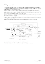
Figure 2 - Block diagram of the LP 31 Series / 8-10-15-20 kVA UPS, mains failure


No interruption or alteration will ever be noticed in the output power. 


In the event of an extended mains failure, the output converter will stop when the battery energy has 
been used up. 
At this point, the UPS is no longer able to power the connected equipment. 
 
When the mains is re-established within tolerance, the output converter will be supplied again by the 
input converter and the batteries will be recharged, making them ready to support future power 
failures. 

Summary of Contents for Digital Energy LP 31 Series

Page 1: ...rgy Uninterruptible Power Supply LP 31 Series 8 10 15 20 kVA 400 VAC CE Series 1 Manufactured by GE Consumer Industrial SA General Electric Company CH 6595 Riazzino Locarno Switzerland T 41 0 91 850 5...

Page 2: ...itions 4 2 3 Mains Failure 4 2 4 Bypass operation 5 3 EXTERNAL DESCRIPTION 6 3 1 Front and Rear Panel 6 3 2 The LCD screen 6 3 3 Alarm Conditions 7 4 STANDARD FEATURES 8 5 INTERFACING 9 5 1 ComConnect...

Page 3: ...tely Energy is stored as Direct Current DC but input and output energy must be Alternating Current AC in sine wave form The UPS therefore contains an input converter AC to DC and an output converter D...

Page 4: ...2 3 Mains Failure In the event of a mains power failure i e absent or outside tolerance the output converter uses the energy reserve stored in the battery to continue to produce AC power ensuring unb...

Page 5: ...onverter is unable to deliver the demanded output power overload overtemperature the bypass switch will automatically transfer the load to the mains If bypass operation is caused by an overload situat...

Page 6: ...terfaces ComConnect RS232 LCD screen 2 x 16 characters Potentialfree contacts Push buttons down enter reset up CardConnect slot Buzzer resettable Manual bypass switch Inverter on off switch Input Outp...

Page 7: ...e Service information on internal components fan speed internal DC voltage internal temperature levels peak input voltage mean bypass input voltage mean output voltage Start of a quick battery test Fo...

Page 8: ...m level The test will after a complete recharge result in new autonomy predictions Communications port ComConnect 9 pin Sub D male plug No load shutdown Whenever the load is 2 of the maximum load and...

Page 9: ...red conditions include mains voltage availability discharge level of batteries temperature of the batteries interactive control and diagnostic information for stand alone and network systems Interface...

Page 10: ...o the user 6 2 Alarm Boxes An interface box linked to the ComConnect port the VIC RELAYBOX 01 translates the ComConnect signals to five independent changeover contacts with a maximum switching capacit...

Reviews: