OPM_STS_400_25A_100_1GB_V011
38
GE DE STS: installation and operating manual 1.1 (GB)
Digital Energy
™
Static Transfer Switch
g
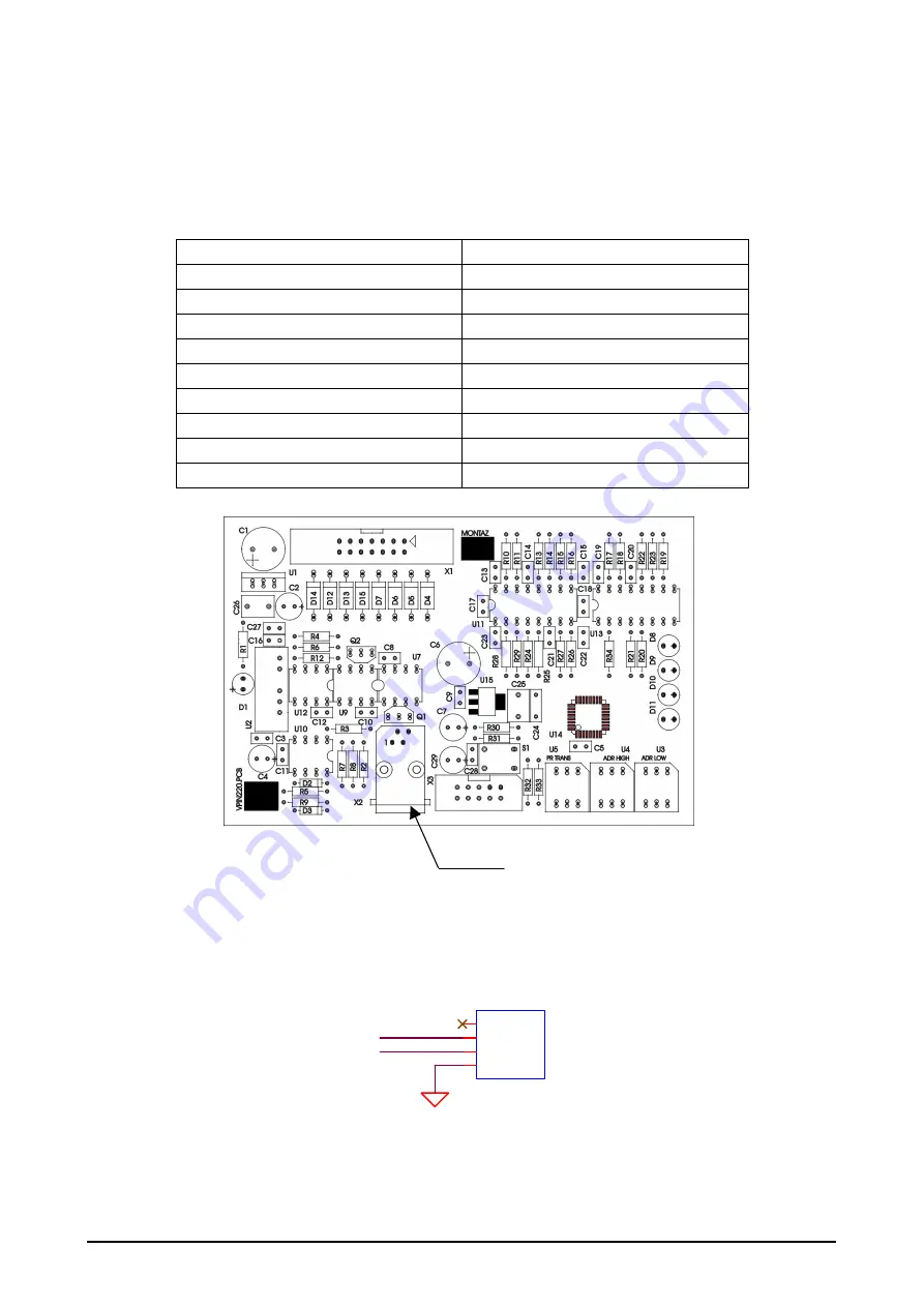
The transmission speed is selected by setting a switch on the PCB (printed board). The switch is marked as
PR TRANS
and it has
16 positions. Table 8 below shows the settings and corresponding transmission
speed.
Table 8
PR TRANS setting
Transmission speed in bauds
0 600
1 1200
2 2400
3 4800
4 9600
5 19200
6 38400
7 57600
8 115200
Figure 13. PCB of Communication Interface Module CI-M1
The X2 user connector is a socket type RJ10 with outlets as in figure 14.
Figure 14. RS485 connector
X2
ISO GND
A485
X2
RJ10
1
2
3
4
V+
A485
B485
GND
B485


