OPM_STS_400_25A_100_1GB_V011
8
GE DE STS: installation and operating manual 1.1 (GB)
Digital Energy
™
Static Transfer Switch
g
2.1 Warranty
GE Digital Energy, operating through its authorized agents, warrants that the standard products will be free of
defects in materials and workmanship for a period of 24 months after the date of invoice, or such other period
as may be specified.
NOTE
This warranty does not cover failures of the product which result from incorrect
installation, misuse, alterations by persons other than authorized agents, or abnormal
operating conditions
2.2 Description
Static Transfer Switches type STS-400-XX-3/4 (four 3-pole models STS-400-25/40/63/100-3 and three 4-pole
models STS-400-25/40/63-4) are designed for switching between two alternative electrical power sources
without interruption of the power supplied to the load. The neutral wires in the 3-pole STS type are connected
together, whereas the neutral wires in the 4-pole type are being switched the same way as the phase wires.
The static transfer switch (STS) is connected to two sources of electrical power with terminals called X01
PRIMARY SOURCE and X02 SECONDARY SOURCE. The rated voltage of both sources is 400V AC phase-
to-phase and the frequency is 50Hz. Depending on the current settings and the state of the system, one of the
two sources (either the PRIMARY SOURCE or the SECONDARY SOURCE) is “connected” to the output
terminal called X03 STS OUTPUT. Possible methods for transferring the load from one source to other are
explained in chapter 4.
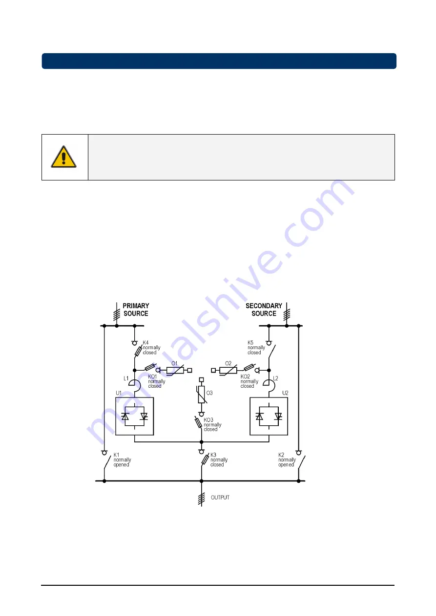
Figure 1. Electrical diagram of Static Transfer Switch (STS) with manual bypasses
Each single line on the diagram represents three wires inside the 3-pole STS and four wires inside the 4-pole
STS.
PRIMARY SOURCE, SECONDARY SOURCE and STS OUTPUT connections consist of five wires each
including Protective Earth (PE).
2 - Introduction


