Chapter 1. Calibration
8
DigitalFlow™ XGM868i Service Manual
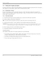
1.7 Testing Totalizer Outputs
Totalizer outputs may be added to the Model XGM868i by installing an appropriate option card in
Slot 1
. This option
card contains two or four totalizer outputs, which are designated A, B, C and D.
1.7.1 Preparing for Testing
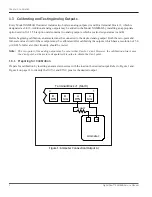
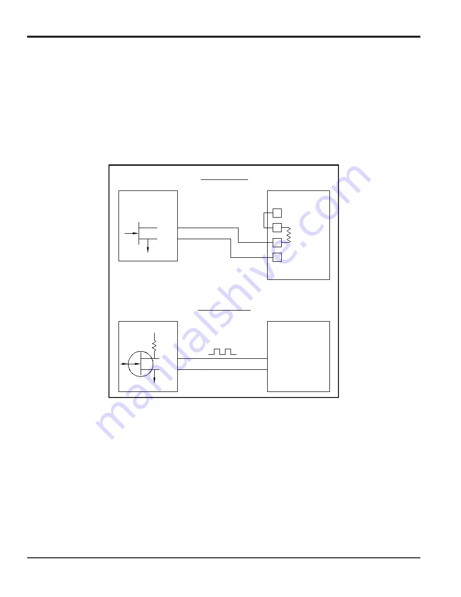
Prepare for the testing procedure by connecting a pulse counter to the desired output of the option card. See Figure 2
for totalizer output wiring, and Figure 4 on page 12 to identify the
OUT(+)
and
RTN(-)
pins for
Output A
on terminal block
J2.
Figure 2: Totalizer and Frequency Output Wiring
1.7.2 Testing the Output
1.
From the
Keypad Program
, press the right arrow key to scroll to the
CALIB
menu. Press
[Enter].
2.
In the
Cal
window, scroll to
Slot 1
. Press
[Enter].
Note:
The
Slot 1
option only appears at the above prompt if an option card is installed in this slot.
3.
Scroll to the desired
Output.
(
Output A
will be used as an example in this manual.) Press
[Enter].
IMPORTANT:
The procedure for testing all the outputs is the same. However, when testing another output, be sure to
reconnect the pulse counter at terminal block
J2
. See
for the correct pins.
OUT
RTN
IN
Common
Load
Volts -
(Common)
Volts +
(Int. Pwr. Sup.)
OUT
RTN
+5V
200
:
Transmitter
Transmitter
Pulse Counter
Frequency Counter
Totalizer Output
Frequency Output
Summary of Contents for DigitalFlo XGM868i
Page 2: ......
Page 4: ...ii no content intended for this page ...
Page 44: ...Chapter 4 Parts Replacement DigitalFlow XGM868i Service Manual 36 ...
Page 48: ...40 DigitalFlow XGM868i Service Manual no content intended for this page ...
Page 70: ...62 DigitalFlow XGM868i Service Manual no content intended for this page ...
Page 78: ...Warranty 70 DigitalFlow XGM868i Service Manual no content intended for this page ...
Page 79: ......


