March 2008
1-12
Installation
Wiring the Ethernet
Interface
A modified GS868 can use the Ethernet interface to communicate to
an internal network. An optional Ethernet card with a unique MAC
(IP) address (installed only in slots 5 or 6) includes an RJ45
connector. To connect the Ethernet-enabled GS868 to the network,
insert the jack of an RJ45 cable into the RJ45 connector, route the
cable through the bottom of the GS868, and wire the other end of the
cable to the Ethernet network according to the manufacturer’s
instructions. An external connection is required between the Ethernet
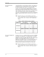
option card and the GS868’s RS232 connector, as shown in Table 1-2
below.
Note:
The MAC address for a specific GS868 is included with
customer documentation. For more information on setting up
the MAC address, refer to Chapter 6 of the
Programming
Manual.
Wiring the MODBUS/TCP
Interface
Customers can also use a modified GS868 that provides a MODBUS/
TCP interface to communicate to an internal network. An optional
MODBUS/TCP card with a unique MAC (IP) address (installed only
in slots 5 or 6) includes an RJ45 connector. To connect the
MODBUS/TCP-enabled GS868 to the network, insert the jack of an
RJ45 cable into the RJ45 connector, route the cable through the
bottom of the GS868, and wire the other end of the cable to the
Ethernet network according to the manufacturer’s instructions.
Note:
The MAC address for a specific GS868 is included with
customer documentation. For more information on setting up
the MAC address, refer to Chapter 6 of the Programming
Manual.
Table 1-2: RS232 to Ethernet Interconnections
GS868 Type
Terminal Block
Terminal Block
Wall Mount
RS232 on Main Board TB1 on Ethernet Card
TX
Pin 1
RX
Pin 2
RTN
Pin 3
Rack Mount
RS232 on Main Board TB2 on Ethernet Card
TX
Pin 1
RX
Pin 2
RTN
Pin 3
Summary of Contents for DigitalFlow GS868
Page 6: ...Chapter 1...
Page 28: ...Chapter 2...
Page 40: ...Chapter 3...
Page 41: ...Operation Introduction 3 1 Powering Up 3 2 Using the Display 3 3 Taking Measurements 3 5...
Page 49: ...Chapter 4...
Page 50: ...Specifications General 4 1 Electrical 4 2 Operational 4 4 Transducer 4 4 Flowcell 4 5...
Page 56: ...Appendix A...
Page 57: ...CE Mark Compliance Introduction A 1 Wiring A 1 External Grounding A 1...
Page 59: ...Appendix B...
Page 60: ...Data Records Option Cards Installed B 1 Initial Setup Data B 2...
Page 64: ...Appendix C...
Page 71: ...Appendix D...
Page 72: ...Measuring P and L Dimensions Introduction D 1 Measuring P and L D 1...


