Operation
3-3
March 2008
Using the Display
The Model GS868 display is divided into a left pane and a right pane.
The two screen panes can be set independently to display any of the
available measurement or diagnostic parameters. The components of
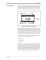
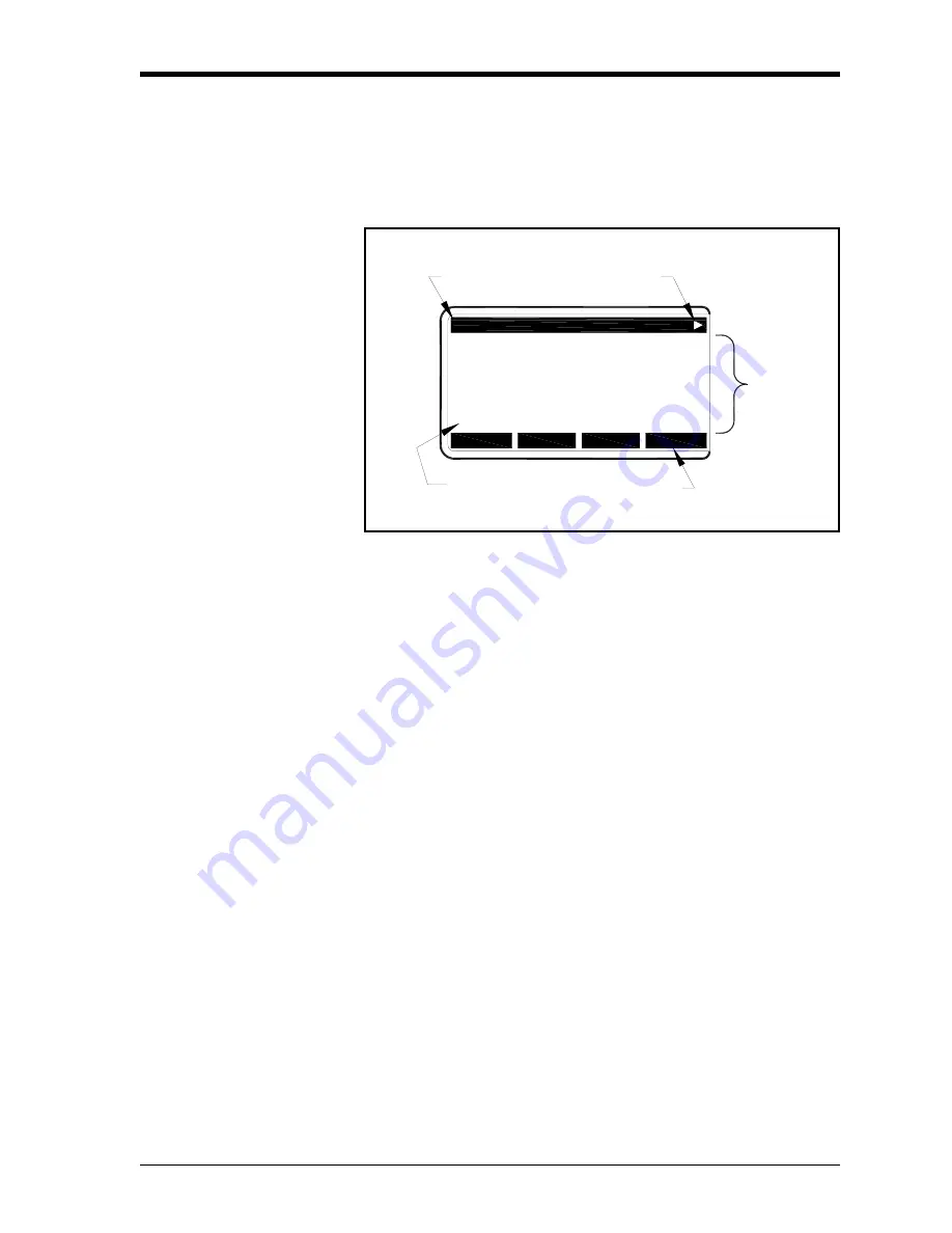
a typical measurement mode screen are shown in Figure 3-2 below.
Figure 3-2: Display Screen Components
Both panes of the display screen are continuously updated, but only
one pane at a time may be programmed or changed. To select a pane,
press the corresponding side of the
[SCREEN]
key on the keypad. The
currently selected screen pane will have function names in the option
bar, while the other screen pane will have a blank option bar. See the
Programming Manual
for detailed instructions on using the keypad.
As shown in Figure 3-2 on page 3-3, each pane of the display screen
is divided into the following three general areas:
•
the locator bar
•
the prompt area
•
the option bar.
The upper portion of the screen pane is called the
locator bar
. While
the meter is taking measurements, the locator bar displays the name
of the currently selected site file. In addition, the locator bar identifies
the task that is currently being performed and the status of that task.
For example, pressing the
[PROG]
key on the keypad will cause the
locator bar to display
“PROGRAM”
and
“Start”
to indicate that the meter
is ready to be programmed from the start of the
User Program
.
Velocity
Ft/s
6.95
Ch1 E1: Low Signal
Pointer
Prompt
Area
Locator Bar
Option Bar
Error Code
Ch1 no label
gSITE
CH1
CH2
SUM
DIF
Summary of Contents for DigitalFlow GS868
Page 6: ...Chapter 1...
Page 28: ...Chapter 2...
Page 40: ...Chapter 3...
Page 41: ...Operation Introduction 3 1 Powering Up 3 2 Using the Display 3 3 Taking Measurements 3 5...
Page 49: ...Chapter 4...
Page 50: ...Specifications General 4 1 Electrical 4 2 Operational 4 4 Transducer 4 4 Flowcell 4 5...
Page 56: ...Appendix A...
Page 57: ...CE Mark Compliance Introduction A 1 Wiring A 1 External Grounding A 1...
Page 59: ...Appendix B...
Page 60: ...Data Records Option Cards Installed B 1 Initial Setup Data B 2...
Page 64: ...Appendix C...
Page 71: ...Appendix D...
Page 72: ...Measuring P and L Dimensions Introduction D 1 Measuring P and L D 1...

