GE
HEALTHCARE
D
IRECTION
2307224-100, R
EVISION
6
D
ISCOVERY
LS S
YSTEM
S
ERVICE
M
ANUAL
Chapter 8 - System QC, Calibration and Functional Tests
Page 255
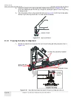
2.) Unscrew all the baseplate screws (shown in
) sufficiently to take the pressure off
the spring washers and allow the baseplate to be adjusted.
3.) Move the gantry to the middle of its travel range.
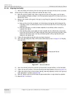
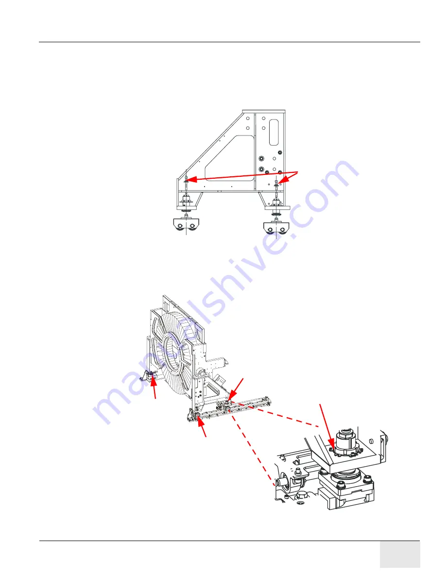
4.) Make sure that the securing screws (shown in
) on the high-load roller adjusters
are closed enough to prevent the rollers from falling off the gantry leg; verify that the roller can
be rotated freely.
Figure 8-15:
Securing Screws on Rollers
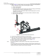
5.) Unscrew and raise the adjuster locking rings with 3-5 turns from the two linear bearing
assembly adjusters and from the front high-load roller Adjusters 1, 2, and 3 (shown in
).
Figure 8-16:
Adjuster Locking Rings
Securing Screws
Adjuster Locking Ring
Adjuster #2
Adjuster #1
Adjuster #3

